1. Home
  2. Devices
  3. Ipsum
  4. IPSUM – wiring and commissioning
  1. Home
  2. Devices
  3. IPSUM – wiring and commissioning

IPSUM – wiring and commissioning

Connecting the weighing panel

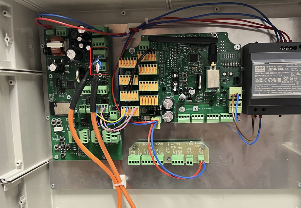
Connect the strain gauge beams in the marked place. Connect the cables in the order from left:

  1. Black
  2. Red
  3. White
  4. Blue
Photo of the IPSUM main board with a red box marking the strain gauge weighing beam terminal where the black, red, white and blue cables connect.

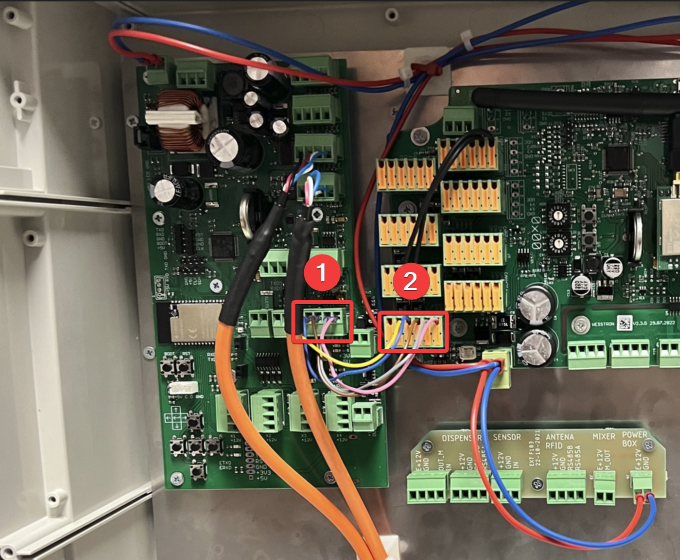
Connect the weighing panel to the main IPSUM board in the marked places [1][2], the cables should be connected in the following order from the left:

  1. Empty slot
  2. Yellow
  3. Blue
  4. Brown
  5. Gray
  6. Pink
Photo of the IPSUM main board with red numbered boxes 1 and 2 marking the weighing panel connection terminals on the main board.

Power connection

Connect the 230VAC power supply from the mains in the place marked as [1], from the left connect PE, N, L. In the place marked as [2] connect the power supply, from the left L, N. In the places marked as [3][4][5] connect the power supply to individual boards, from the left +V, -V.
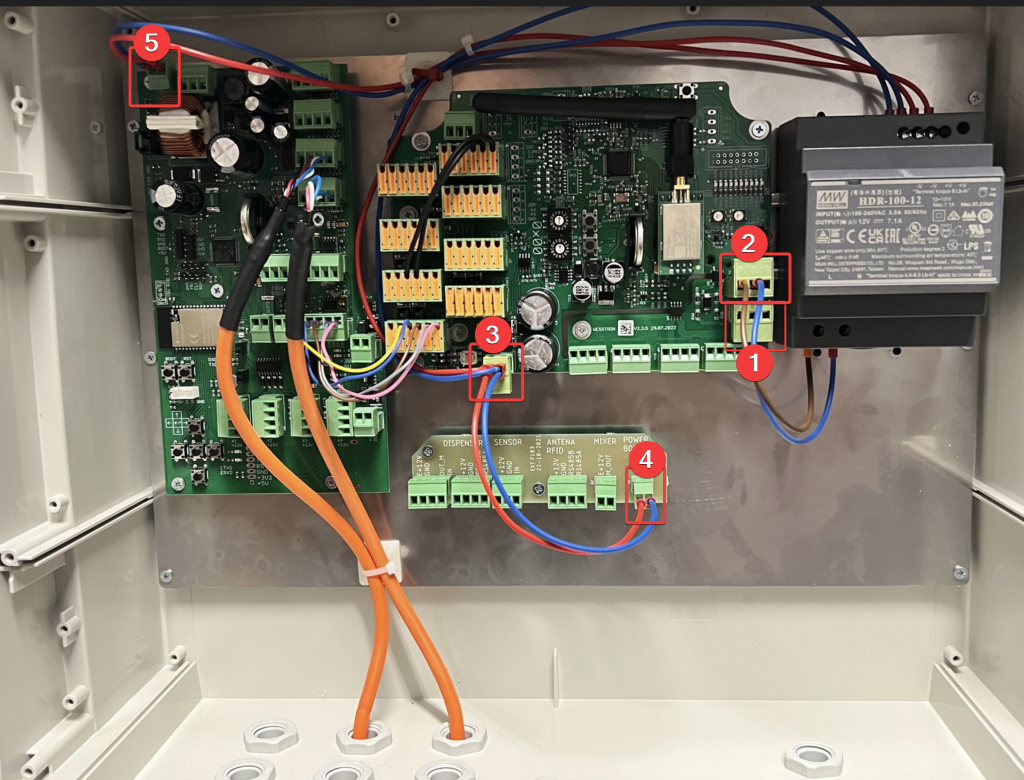
Photo of the IPSUM main board with red numbered boxes 1-5 marking the mains power input and the power distribution terminals to the individual boards.

Connecting the adapter

Connect the dispenser to the place marked as [1], connect the weighing panel to the place marked as [2], connect the feed amount sensor in the feeder to the place marked as [3], connect the RFID antenna to the place marked as [4], connect the stirrer to the place marked as [5] and connect the power supply to the place marked as [6].
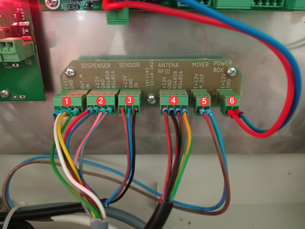
Photo of the IPSUM adapter board with red numbered circles 1-6 marking the connection terminals. Silkscreen labels and pin names printed on the board, from left: DISPENSER covering terminal 1 (E+12V, GND, OUT_M, IN) and terminal 2 (+12V, GND, RS485B, RS485A); SENSOR - terminal 3 (+12V, GND, IN); ANTENA RFID - terminal 4 (+12V, GND, RS485B, RS485A); MIXER - terminal 5 (E+12V, M_OUT); POWER BOX - terminal 6 (E+12V, GND). The board is marked EXT F103 22-10-2021.

Dispenser connection

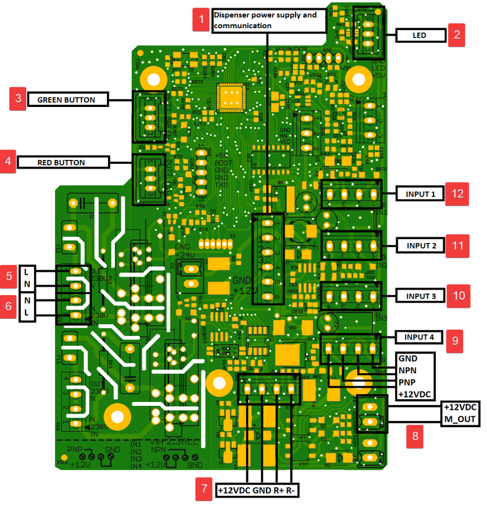
1Dispenser power and communication (cables in order from top: red, blue, pink, gray, yellow, green)
2LED (cables in order from top: blue, white, red)
3Green button (cables in order from top: brown, gray, green)
4Red button (cables in order from top: no cable in first slot, yellow, pink)
5230V Engine power supply
6Engine power supply (cables in order from left: white, brown)
7Adapter connection (cables in order from left: red, blue, pink, gray)
8Stirrer connectior
9Unused
10Sensor in the feeder
11Sensor in the volumetric dispenser
12Unused
Description of the dispenser board outputs
Diagram of the dispenser board with numbered callouts and the exact labels printed next to each terminal: 1 Dispenser power supply and communication, 2 LED, 3 GREEN BUTTON, 4 RED BUTTON, 5 mains terminals L and N, 6 mains terminals N and L, 7 terminal with pins +12VDC, GND, R+, R-, 8 terminal with pins +12VDC and M_OUT, 9 INPUT 4 (with pins GND, NPN, PNP, +12VDC), 10 INPUT 3, 11 INPUT 2, 12 INPUT 1. Additional silkscreen visible on the board: IN1-IN4 with PNP/GND/+12V and NPN/+12V/GND selection, GND +24V, GND +12V, OUT 230V and IN 230V markings.

Next steps

Updated on 2026-07-28
Was this article helpful?

Related Articles

Need Support?
Can't find the answer you're looking for?
Contact Support

Leave a Comment