
This manual describes how to connect the Cloud Box, the Bridge, and one or more separation stations.
Before You Begin
Please also refer to the separate wiring and startup instructions for the devices:
Wiring Diagram
Internet → Cloud Box → Bridge → Station 1 → Station 2 → subsequent stations
If more than one station is connected to the Bridge, the stations must be connected in series.
1. Connecting the Cloud Box
- Plug the Cloud Box into a power source [1].
- Connect the Cloud Box to the Internet using a LAN cable [2].
- Connect the RS422 communication cable [3], which leads to the Bridge, to the Cloud Box.
Description of the RS422 signals from left to right: A, B, Z, Y
Cable: LiYCY 4 × 0.75 mm² Maximum length: 300 m
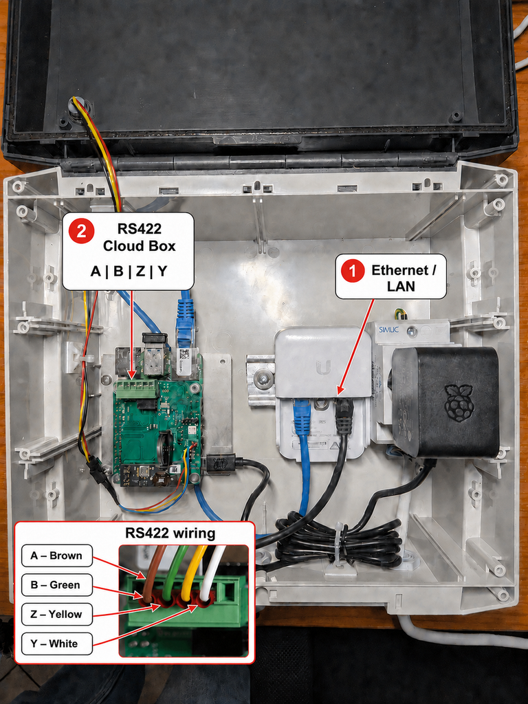
Fig. 1. Power supply, LAN connection, and RS422 port on the Cloud Box.
2. Connecting the Bridge
- Plug the Bridge into a power source [1].
- Connect the RS422 communication cable running from the Cloud Box to the four-pin connector [2] on the Bridge.
- Connect the communication cable leading to the separation station to one of the B | GND | A connectors [3].
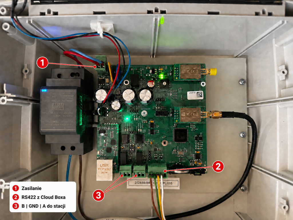
Fig. 2. The Bridge’s power supply and communication ports.
3. Connecting the first separation station
Connect the communication cable running from the Bridge to the A+, B-, and GND terminals in the separation station box.
| Bridge | Separation Station |
|---|---|
| A | A+ |
| B | B- |
| GND | GND |
Next, connect the station’s power supply to the terminals:
- N – neutral wire;
- L – phase wire;
- PE – protective conductor.
The supply voltage depends on the device model and market: Europe – 230 V; United States – 115 V.
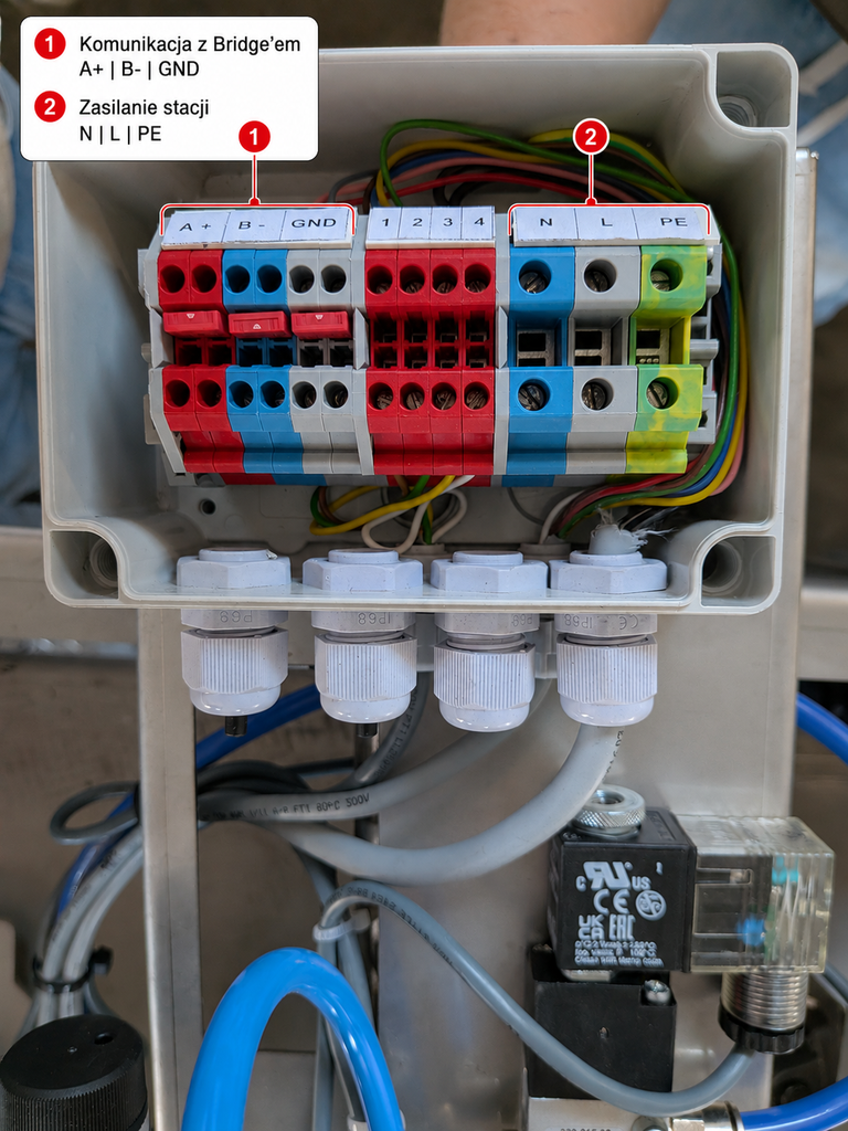
Fig. 3. Communication terminals and power supply for the separation station.
4. Connecting Additional Separation Stations
If there is more than one separation station in the system, connect them in series. Connect the outlet pipe from the first station to the next station, using the same labels:
| Previous Station | Next stop |
|---|---|
| A+ | A+ |
| B- | B- |
| GND | GND |
Connect each subsequent station in the same way.
Important: The last station in the series does not require a terminator. Leave the unused set of A+, B-, and GND terminals unconnected.
5. Call Monitoring
- The Cloud Box is connected to a power source and the Internet.
- The RS422 cable between the Cloud Box and the Bridge has been connected according to the labels.
- The connection between the Bridge and the first station maintains the order of A, B, and GND.
- The remaining terminals were connected according to the designations A+, B-, and GND.
- Each station has been connected to the appropriate power source.
- All wires are properly secured in the terminals.


