
Schematic of the board
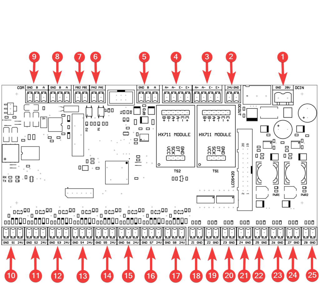
| 1. | 28 VDC input – main power supply of the Sorting Station (from left: GND, +28 VDC) |
| 2. | 24 VDC valve island power supply output (from left: +24 VDC, GND) |
| 3. | Strain gauge 1 output (from left: A+, A-, E-, E+) |
| 4. | Strain gauge output 2 (from left: A+, A-, E-, E+) |
| 5. | RFID antenna (from left: GND, B, A) |
| 6. | Unused output |
| 7. | Alarm line (from left: PB2, PB1) |
| 8. | RS485 communication to Bridge (from left: GND, B, A) |
| 9. | RS485 communication to the next controller (from left: GND, B, A) |
| 10. | Sensor #1 (S1) – sorter entry (from left: GND, control signal, +24 VDC) |
| 11. | Sensor #2 (from left: GND, control signal, +24 VDC) – not used in the two-way station |
| 12. | Sensor #3 (S3) – sorter exit (from left: GND, control signal, +24 VDC) |
| 13. | Sensor #4 (from left: GND, control signal, +24 VDC) – not used in the two-way station |
| 14. | Sensor #5 (S5) – exit to the right (from left: GND, control signal, +24 VDC) |
| 15. | Sensor #6 (S6) – exit to the left (from left: GND, control signal, +24 VDC) |
| 16. | Sensor #7 (from left: GND, control signal, +24 VDC) – not used in the two-way station |
| 17. | Sensor #8 – safety switch input (from left: GND, control signal, +24 VDC) |
| 18. | Valve #1 (Z1) – sorter entry (from left: control output, GND) |
| 19. | Valve #2 (Z2) – sorter exit (from left: control output, GND) |
| 20. | Valve #3 (Z3) – left/right exit (from left: control output, GND) |
| 21. | Valve #4 (from left: control output, GND) – not used in the two-way station |
| 22. | Valve #5 (Z5) – marker 1 (from left: control output, GND) |
| 23. | Valve #6 (Z6) – marker 2 (from left: control output, GND) |
| 24. | Valve #7 (Z7) – animal chasing (from left: control output, GND) |
| 25. | Valve #8 (Z8) – air cut-off (from left: control output, GND) |
Arrangement of sensors and valves at the station
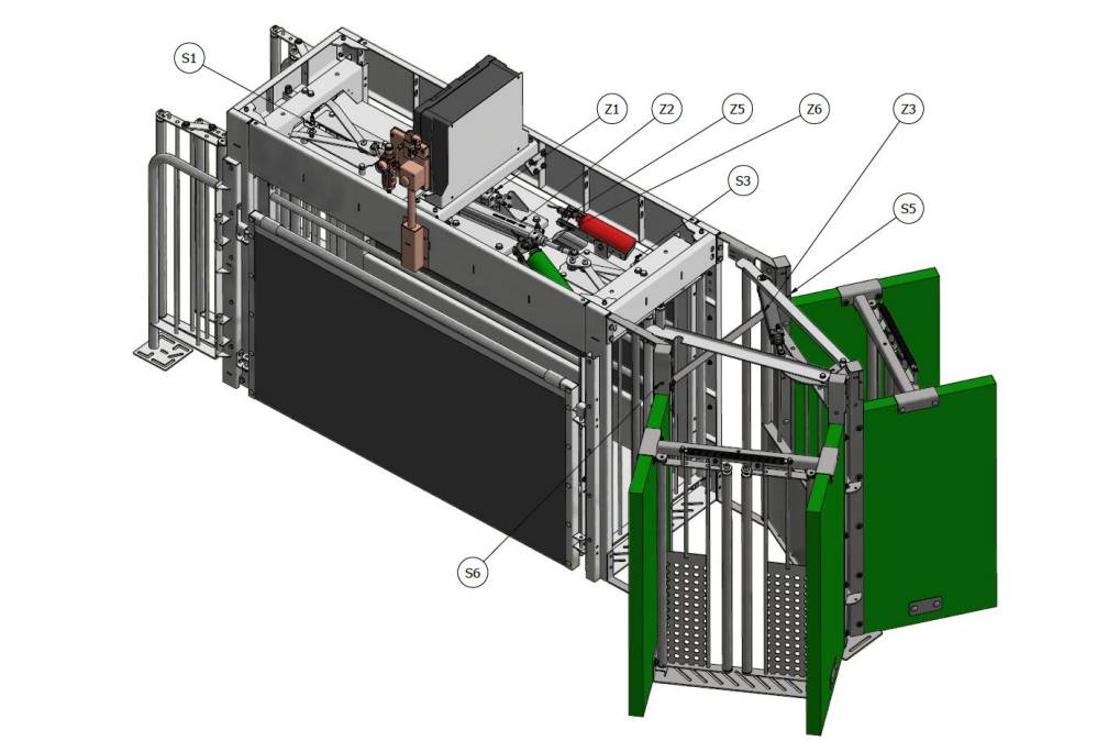
| Z1 | Double-sided pneumatic actuator, stroke 250mm (opening / closing cage entrance) |
| Z2 | Double-sided pneumatic actuator, stroke 250mm (opening / closing cage exit) |
| Z3 | Double-sided pneumatic actuator, stroke 200mm (door selection left / right) |
| Z5 | One-sided mini pneumatic actuator (animal marking – color 1) |
| Z6 | One-sided mini pneumatic actuator one-sided (animal marking – color 2) |
| S1 | Front door closure sensor |
| S3 | Exit door closure sensor |
| S5 | Separation sensor (left exit) |
| S6 | Separation sensor (right exit) |
Connection of valves to the valve terminal
Connect the hoses to the marked valves, the places marked A are responsible for opening the valve, while the places marked B are responsible for closing the valve. In the places marked Z5, Z6, you can connect no hose, connect a hose to only one valve, or connect hoses to both valves.
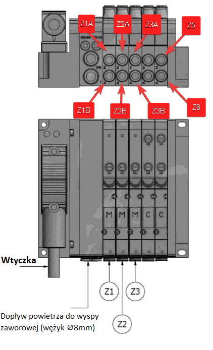
| Z1 | Z1 actuator supply valve |
| Z2 | Z2 actuator supply valve |
| Z3 | Z3 actuator supply valve |
| Z5 | Z5 actuator supply valve |
| Z6 | Z6 actuator supply valve |
Valve coil plug parameters:
Plug dedicated to MA 22 coils: ST222V24, LED, 24V, +/-10%, 10A, 6 – 8mm
Connection of valves on the board
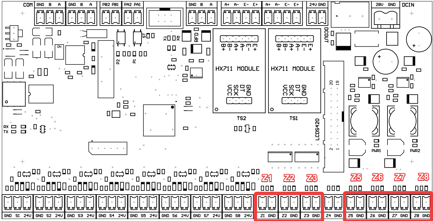
Connect the appropriate cables to the marked two-pin sockets on the board, there is no need to connect the +24VDC power supply.There are cable flags hanging on the cables to help you distinguish them from each other (Z1, Z3, Z5, Z6).
| Socket on the board | Name | Cable color |
| Z1 | Actuator (opening / closing the entry) | White |
| Z2 | Actuator (opening / closing the exit) | Green |
| Z3 | Actuator (left/right selection) | Gray |
| Z5 | Mini actuator (animal marking – color 1) | Purple |
| Z6 | Mini actuator (animal marking – color 2) | Black |
| Z7 | Actuator (chasing away animals) | |
| Z8 | Actuator (air cut-off) |
Sensor connection
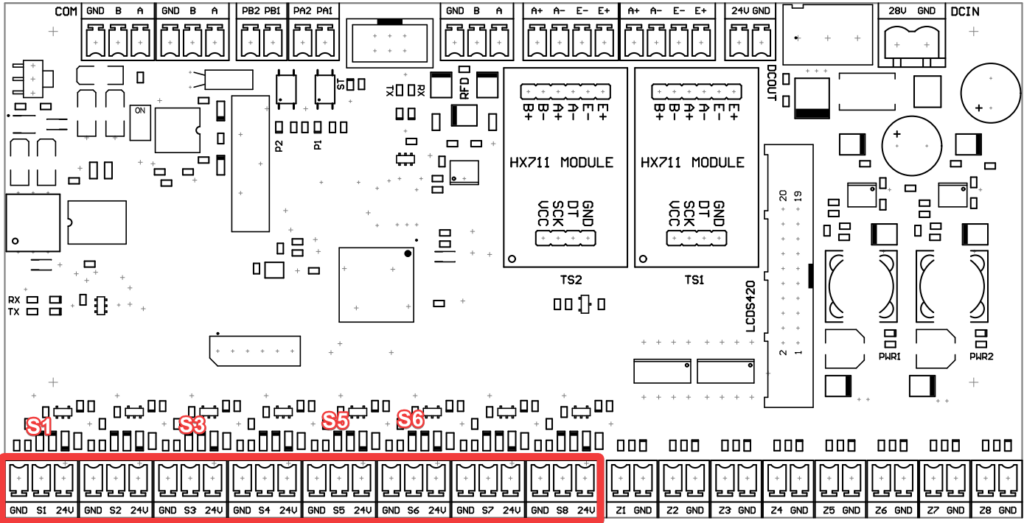
To the marked three-pin sockets, connect the appropriate cables in order from the left:
– GND (blue cable)
– control signal (black cable)
– 12VDC power supply (brown cable)
| Socket on the board | Name |
| S1 | Front gate closure sensor |
| S3 | Sensor for closing the exit gate |
| S5 | Left exit |
| S6 | Right exit |
Sensor parameters:
Inductive sensor, PNP/NO output configuration; 0÷8mm; 10÷30VDC; M12.
Sensor LEDs
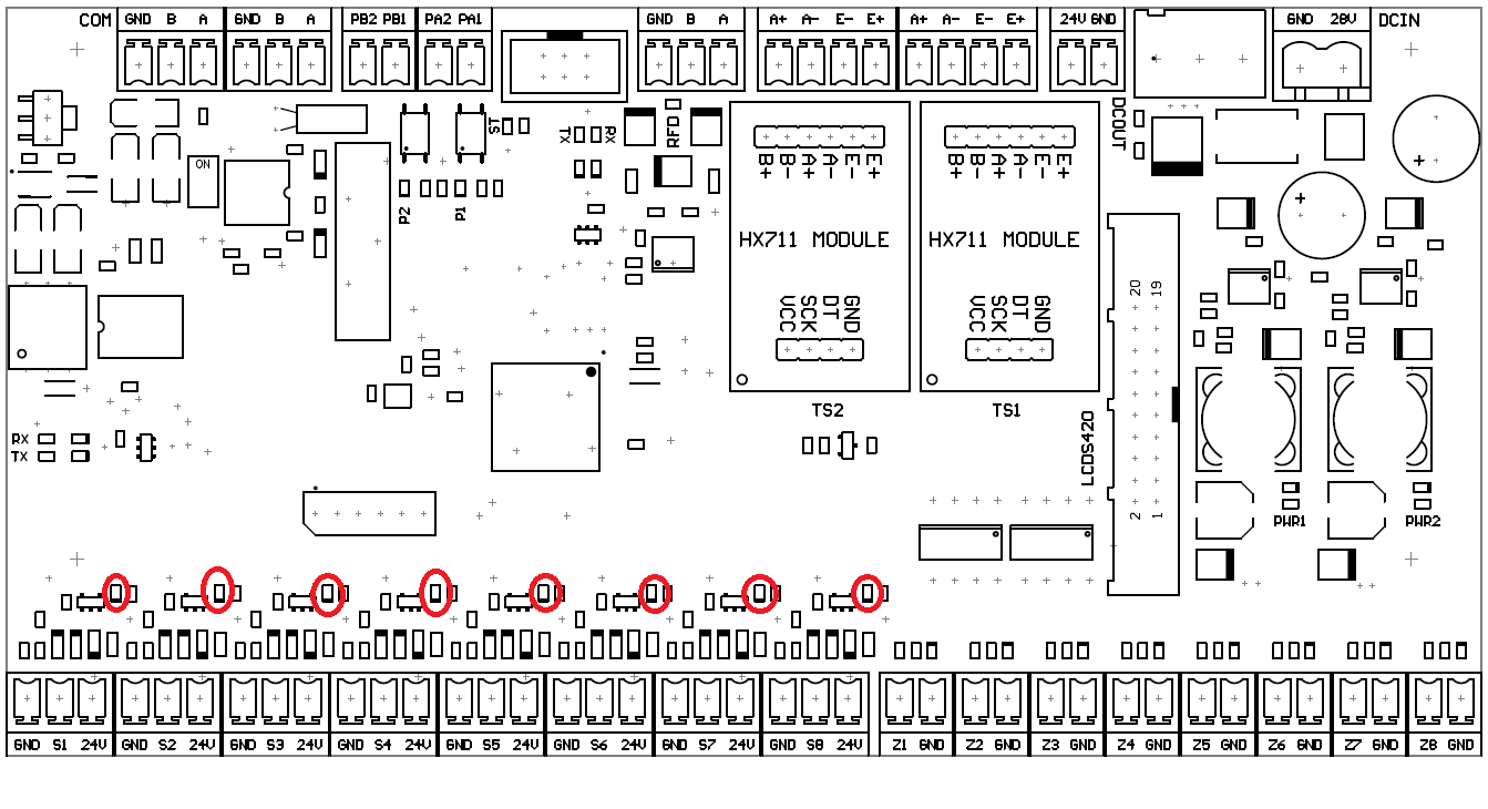
There is a LED above each sensor. If the sensor detects an object in its field of vision, the corresponding LED will turn on, provided the hardware is working properly. The names of the LEDs correspond to the sensor designations on the board.
Connecting the board’s power supply
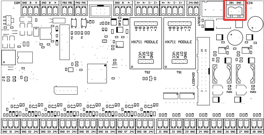
In the marked place, connect the power cable for the board (from the left 28VDC, GND).If the board is powered from the battery, 24VDC will be applied.
Power parameters: Buffer power supply; modular; 38.6W; 27.6VDC; 1.4A; OUT: 1; 370g;
Fuses:
B1 – 0.5A time delay;
B2 – 3.15A time delay.
Connecting the communication
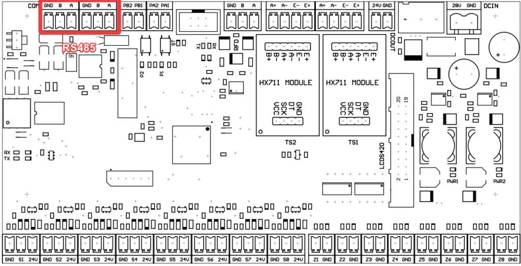
Connect cables to the bridged RS485 connector to the marked terminals. Connect cable A to the terminal marked A, connect cable B to the terminal marked B, and connect the shielded GND cable to the terminal marked GND. If there is a need to connect sorting stations serially, then connect the cables communicating with the Bridge to the terminals on the left, and connect another sorting station to the terminals on the right.
Line termination
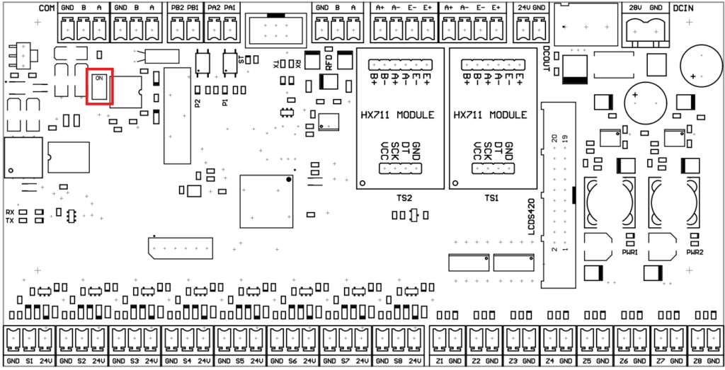
If the sorter is the last device connected on the line then line termination should be enabled on it. This is done by setting the marked switch to ON.
Connection of valve terminal power supply
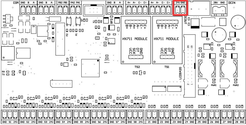
At the marked place, connect the power supply of the valve terminal with the following cables:
– red (24VDC)
– white (GND)
Connection of strain gauge beams
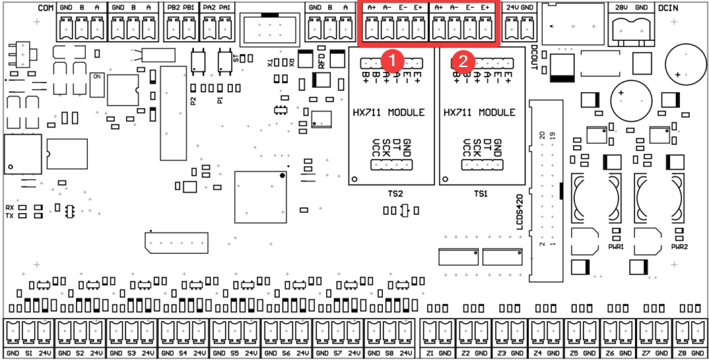
Connect the first strain gauge bar to the marked socket [1].Connect the red cable to the A+ terminal, connect the yellow cable to the A- terminal, connect the white cable to the E- terminal, and connect the green cable to the E+ terminal.Connect the second strain gauge bar similarly to the second terminal [2].For convenience, there are cable flags (TS1, TS2) on the cables.
Connecting an alarm line
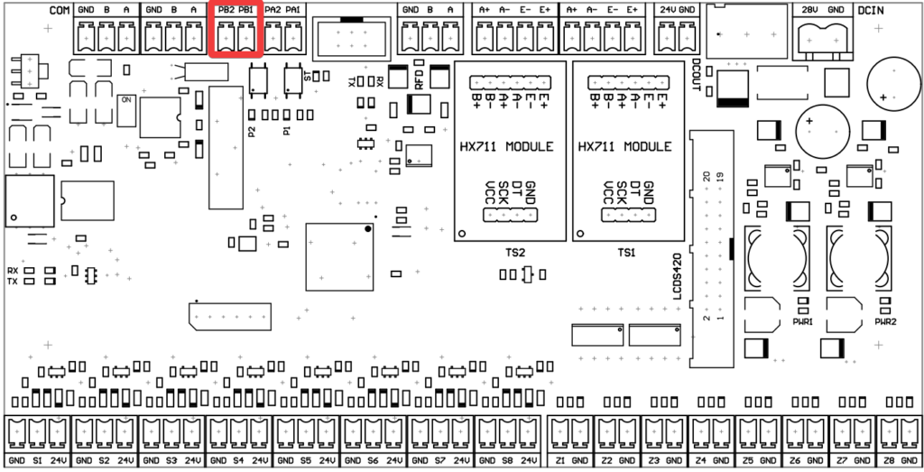
A solid-state output can be connected to the alarm line.If a fault is reported during operation, the device breaks the line circuit, thus triggering an alarm.
RFID antenna connection
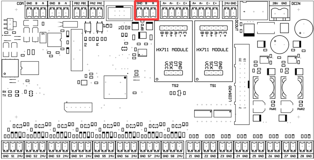
Connect the GND wire to the terminal labeled GND, the B wire to the terminal labeled B, and the A wire to the terminal labeled A.


