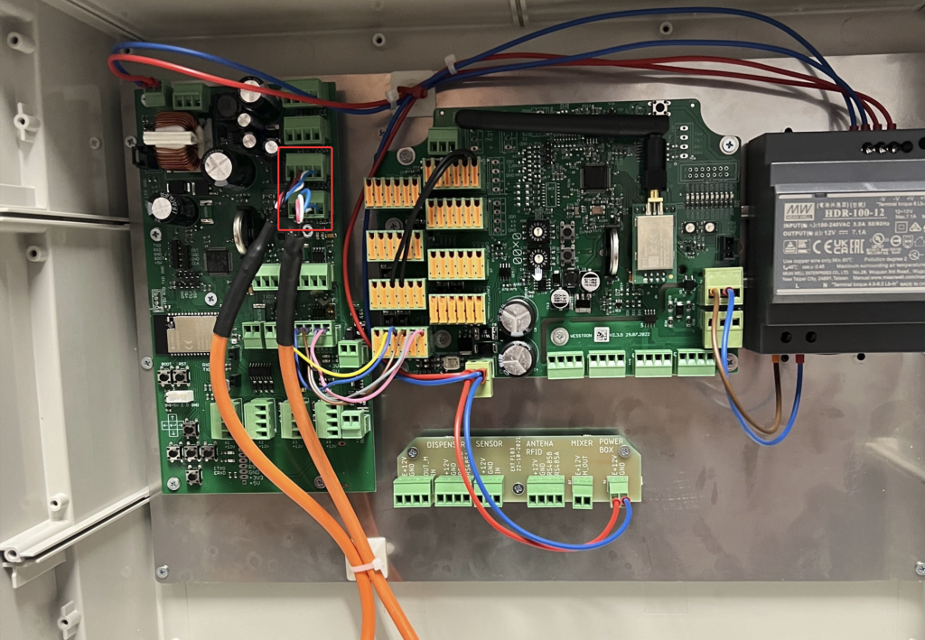
Connecting the weighing panel
Connect the strain gauge beams in the marked place. Connect the cables in the order from left:
- Black
- Red
- White
- Blue
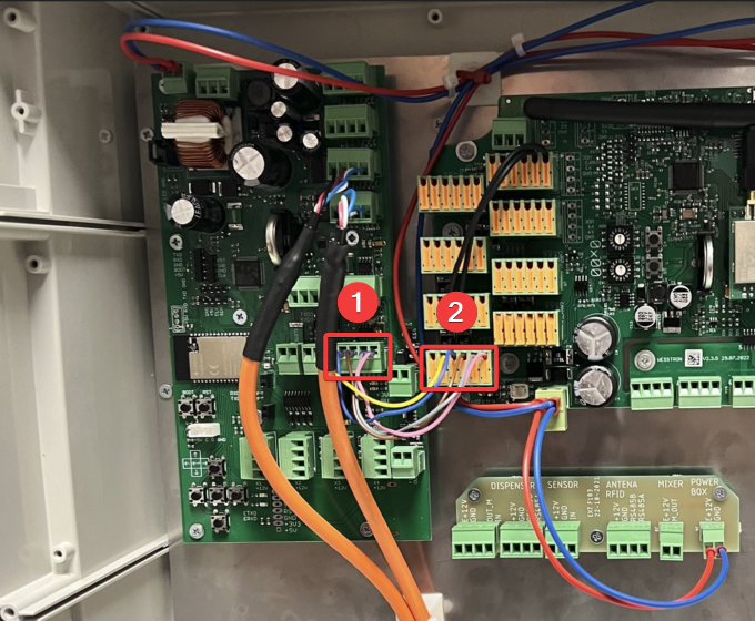
Connect the weighing panel to the main IPSUM board in the marked places [1][2], the cables should be connected in the following order from the left:
- Empty slot
- Yellow
- Blue
- Brown
- Gray
- Pink
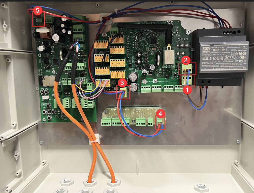
Power connection
Connect the 230VAC power supply from the mains in the place marked as [1], from the left connect PE, N, L. In the place marked as [2] connect the power supply, from the left L, N. In the places marked as [3][4][5] connect the power supply to individual boards, from the left +V, -V.
Connecting the adapter
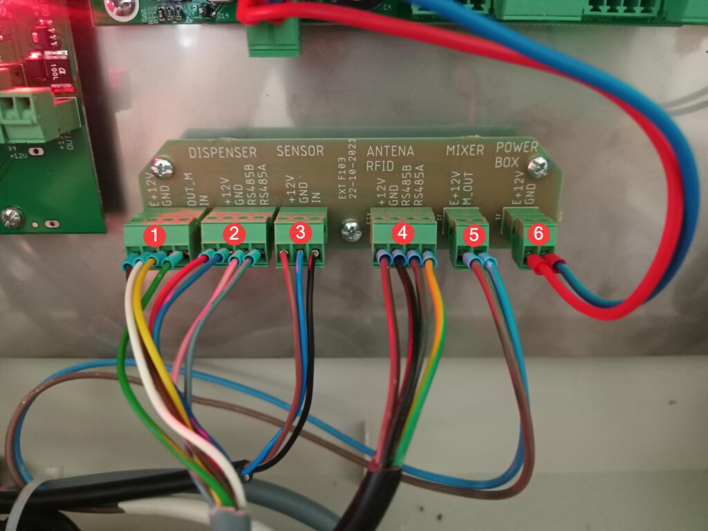
Connect the dispenser to the place marked as [1], connect the weighing panel to the place marked as [2], connect the feed amount sensor in the feeder to the place marked as [3], connect the RFID antenna to the place marked as [4], connect the stirrer to the place marked as [5] and connect the power supply to the place marked as [6].
Dispenser connection
| 1 | Dispenser power and communication (cables in order from top: red, blue, pink, gray, yellow, green) |
| 2 | LED (cables in order from top: blue, white, red) |
| 3 | Green button (cables in order from top: brown, gray, green) |
| 4 | Red button (cables in order from top: no cable in first slot, yellow, pink) |
| 5 | 230V Engine power supply |
| 6 | Engine power supply (cables in order from left: white, brown) |
| 7 | Adapter connection (cables in order from left: red, blue, pink, gray) |
| 8 | Stirrer connectior |
| 9 | Unused |
| 10 | Sensor in the feeder |
| 11 | Sensor in the volumetric dispenser |
| 12 | Unused |