1. Home
  2. Devices
  3. Nutri One
  4. How to wire up dispensers to Connector and Connector Extension?
  1. Home
  2. Devices
  3. Nutri Group
  4. How to wire up dispensers to Connector and Connector Extension?

How to wire up dispensers to Connector and Connector Extension?

This article describes all the steps you need to follow to properly wire up dispensers to Connector and Connector Extension.
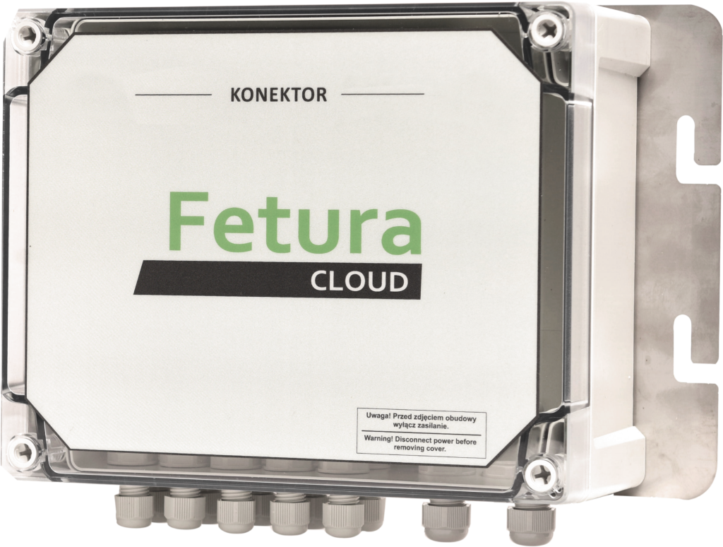
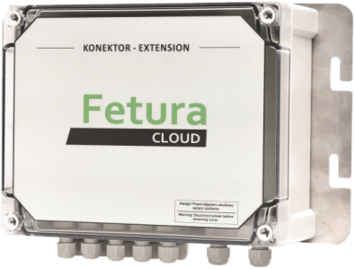
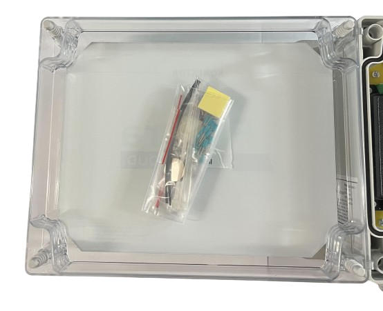
NOTE! Inside the housing there are additional components to be used when wiring dispensers. Take care that they do not fall out when opening the device case.

Open Connector housing viewed from above showing a sealed bag of extra wiring accessories placed inside, which must not fall out when opening the case.

Connector

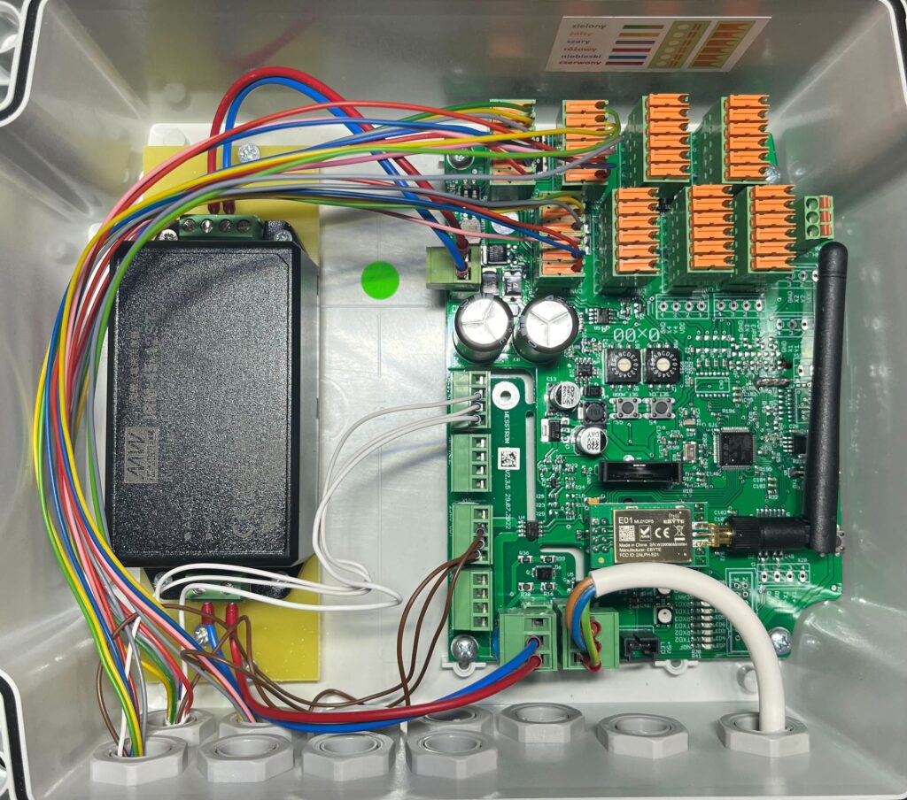
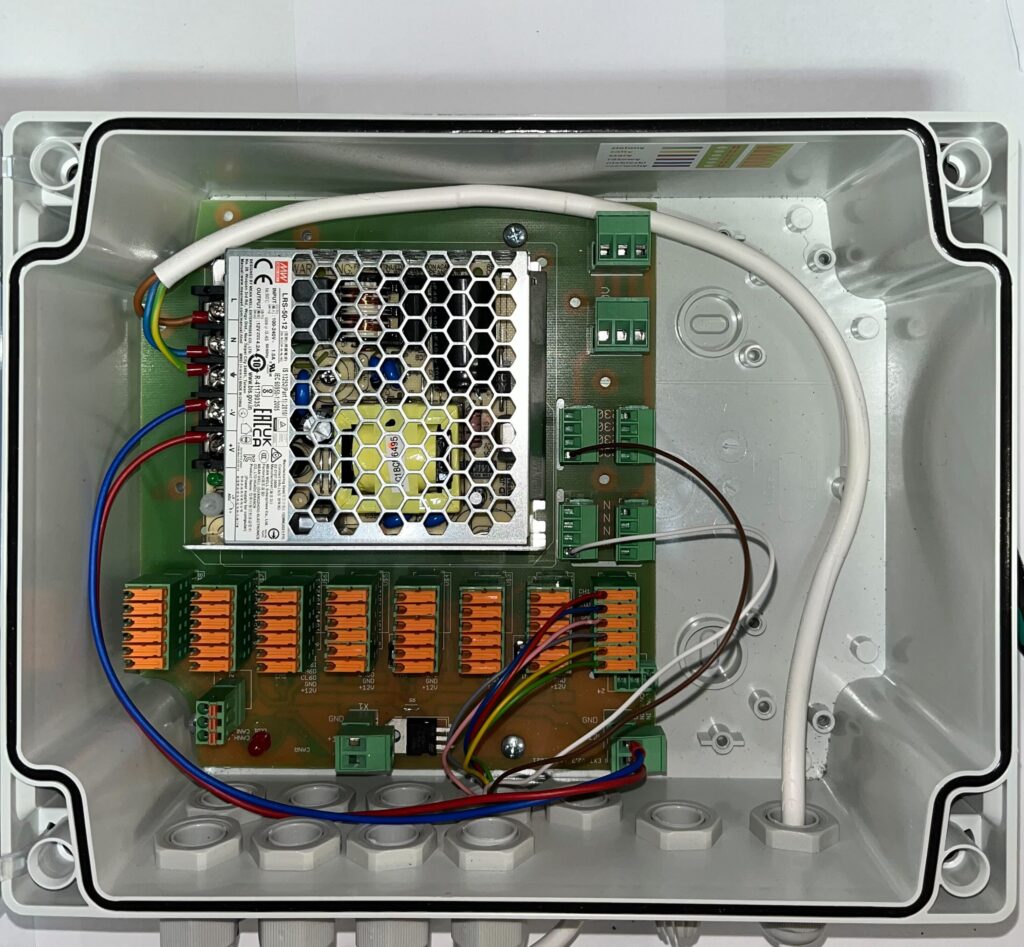
Connector in the factory state has the main power supply and DC power supply connected and is prepared for wiring dispensers.
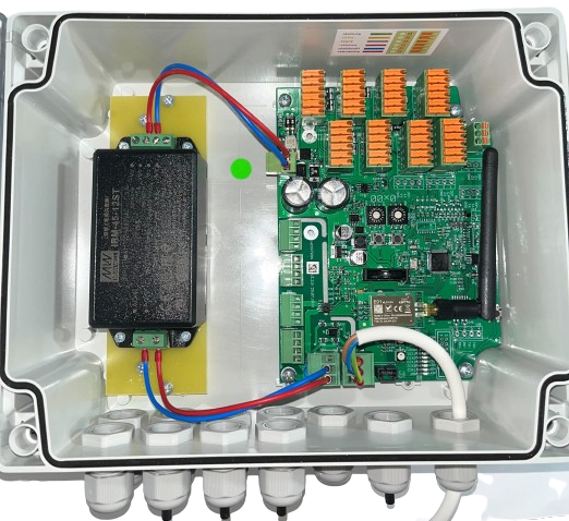
Open Connector case in factory state, showing the green control board with orange terminal blocks and the black DC power supply module already wired, ready for dispenser connections.

Wiring a single dispenser

Enter the cable from the dispenser number 1 into the housing of the Connector and remove 35-40 cm of insulation.
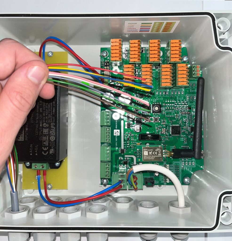
Hand feeding the multi-colored dispenser cable (red, blue, pink, gray, yellow, green wires) into the open Connector case before wiring it to the board.

Remove the plug from dispenser number 1
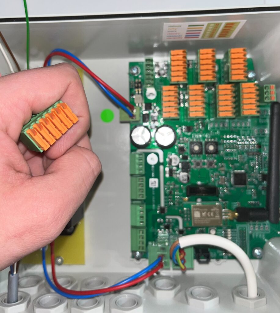
Hand holding the small orange plug connector removed from dispenser 1, ready to have its wires inserted according to the color scheme.

Connect the wires according to the color scheme inside the case.
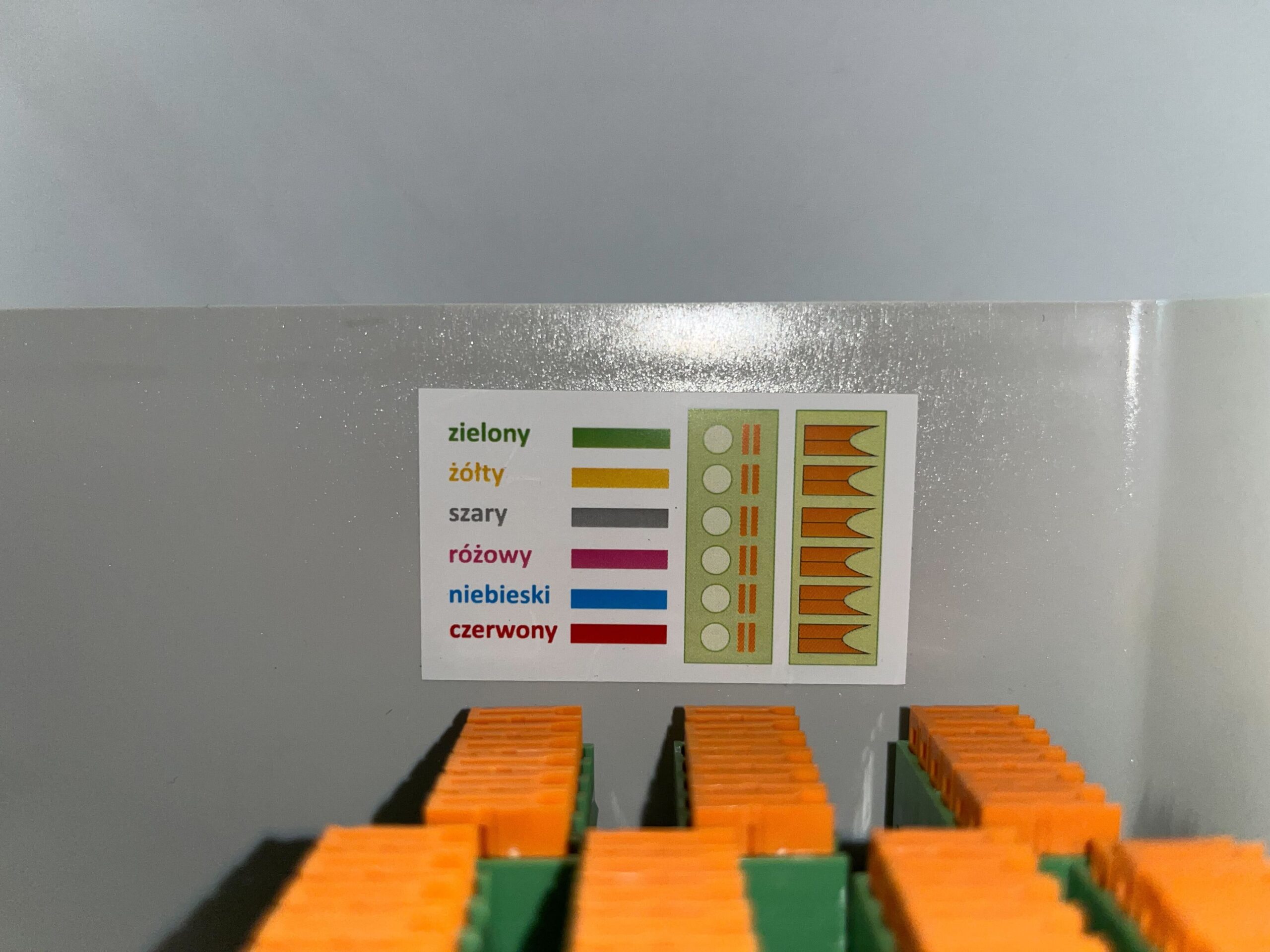
Color-coding label inside the Connector case listing the wire colors (zielony/green, zolty/yellow, szary/gray, rozowy/pink, niebieski/blue, czerwony/red) used to wire the dispensers, mounted above the orange terminal blocks.

Insert the red wire into the plug and lightly tighten the terminal.
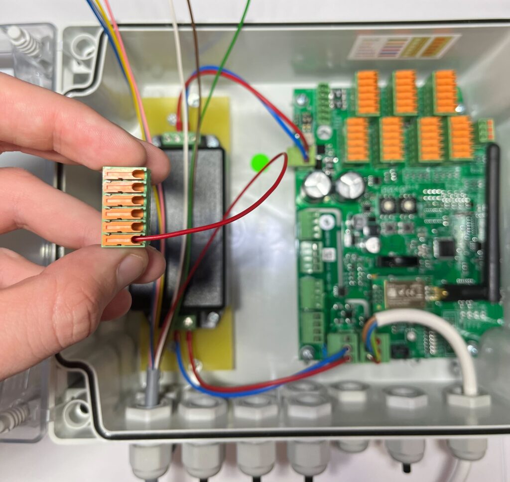
Close-up of a hand inserting the red wire into the dispenser 1 plug connector next to the green reference dot on the control board.

Insert the blue wire and lightly tighten the clamp.
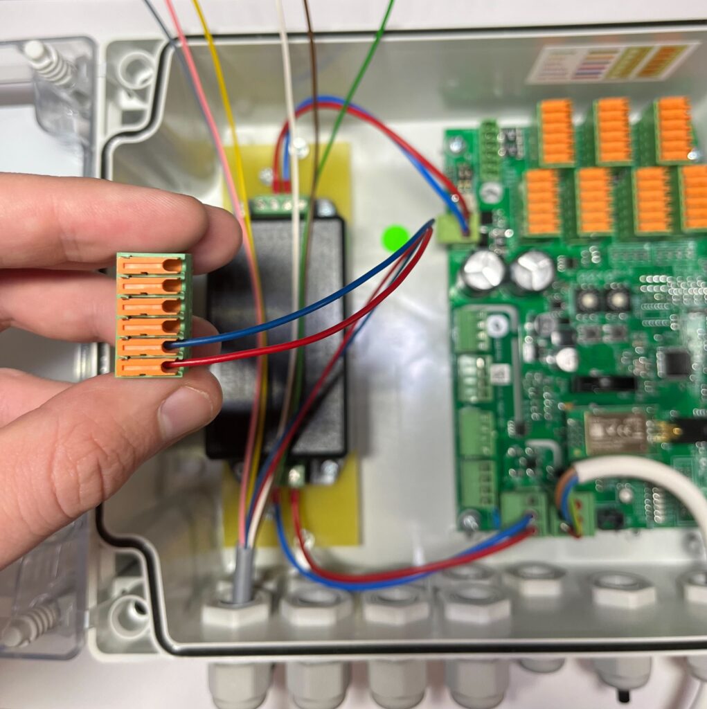
Close-up of a hand inserting the blue wire into the next slot of the dispenser 1 plug connector.

Insert the pink wire and lightly tighten the clamp.
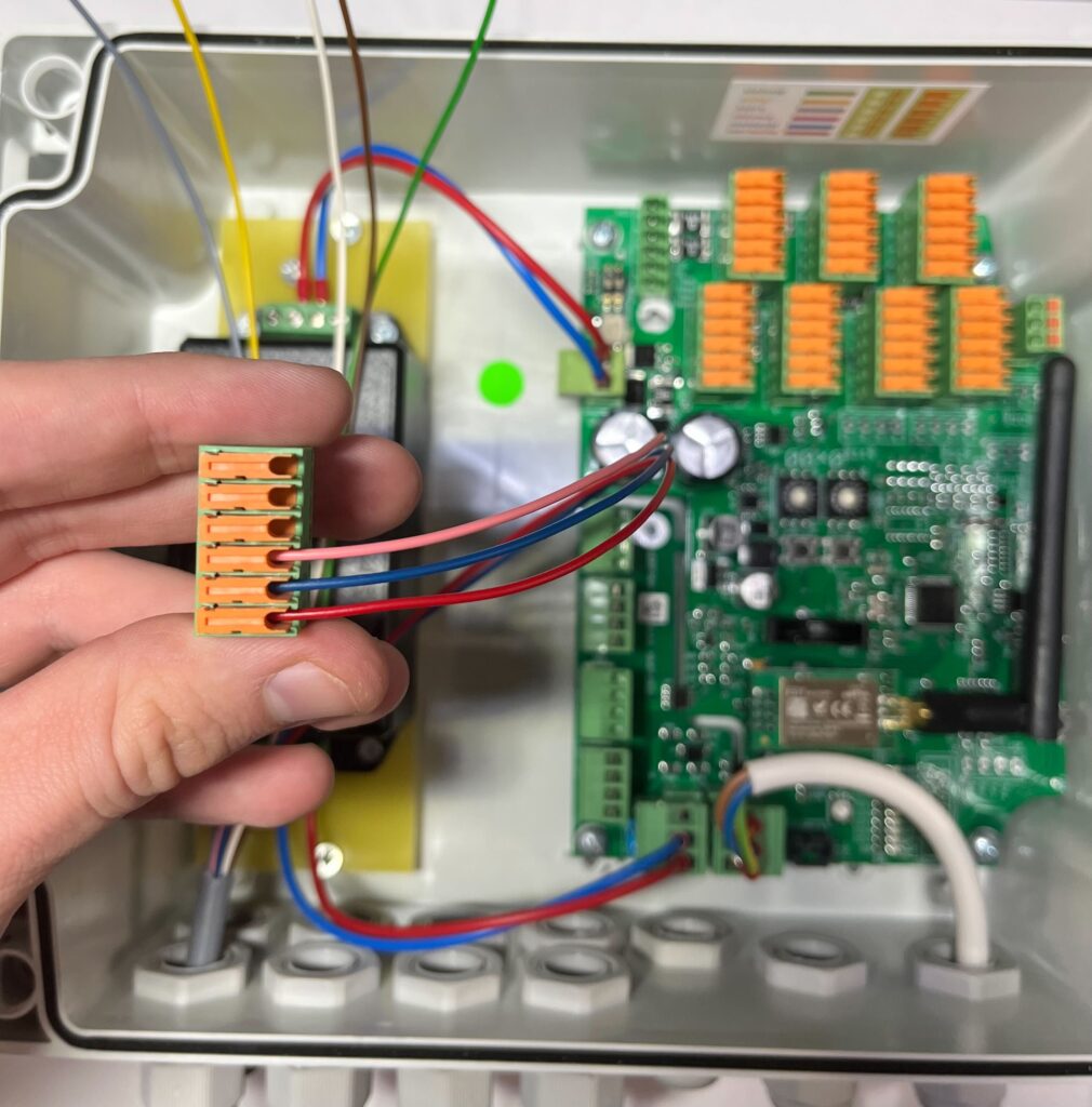
Close-up of a hand inserting the pink wire into the dispenser 1 plug connector, following the color-coded wiring order.

Insert the gray wire and lightly tighten the clamp.
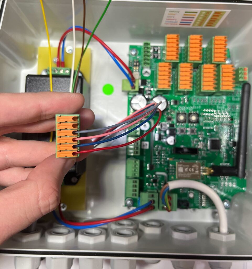
Close-up of a hand inserting the gray wire into the dispenser 1 plug connector.

Insert the yellow wire and lightly tighten the clamp.
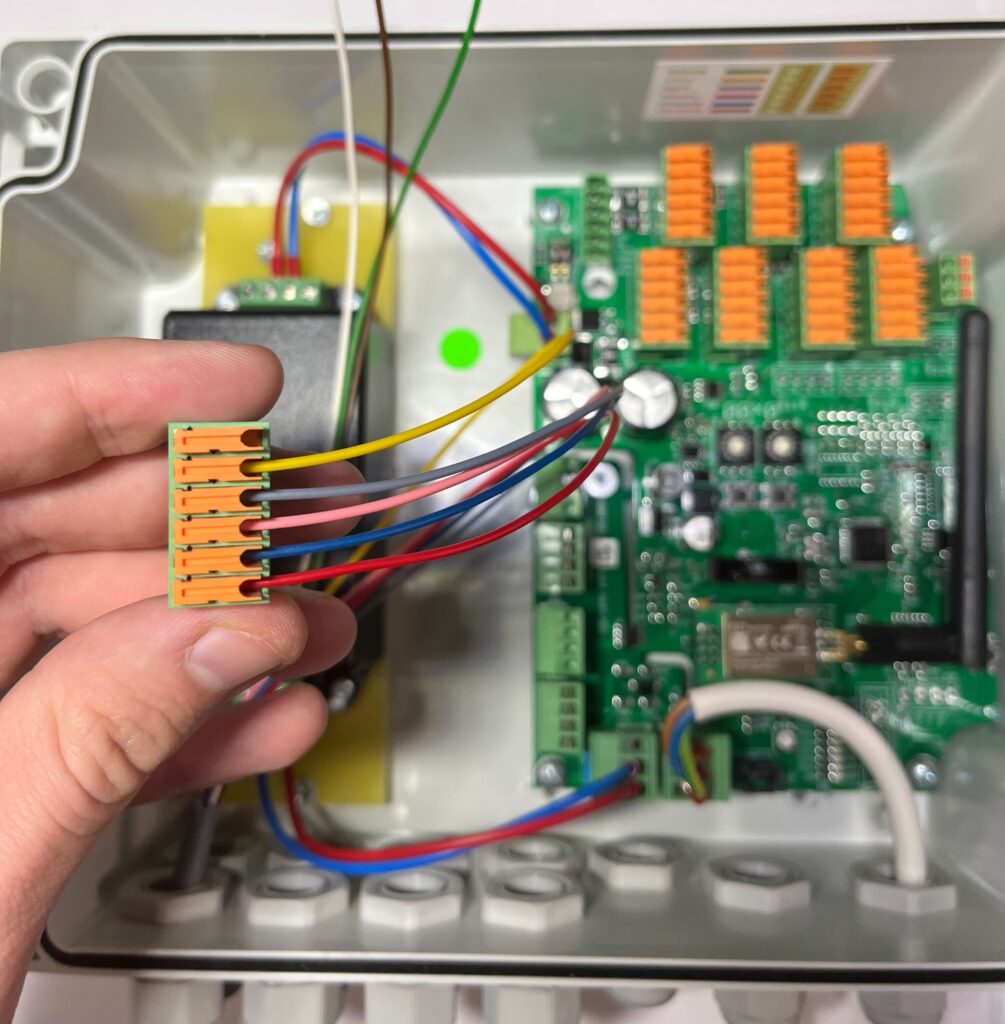
Close-up of a hand inserting the yellow wire into the dispenser 1 plug connector.

Insert the green wire and lightly tighten the clamp.
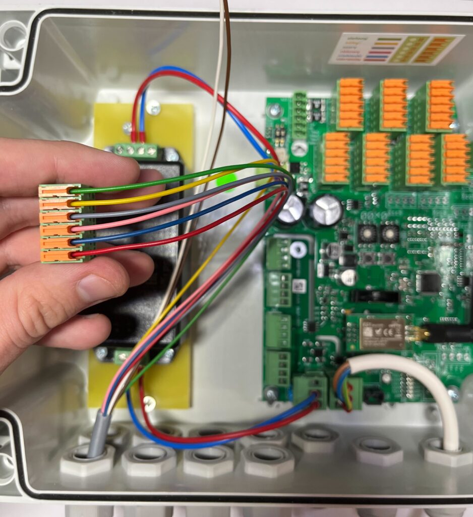
Close-up of the dispenser 1 plug connector with all six color-coded wires (red, blue, pink, gray, yellow, green) fully inserted and tightened.

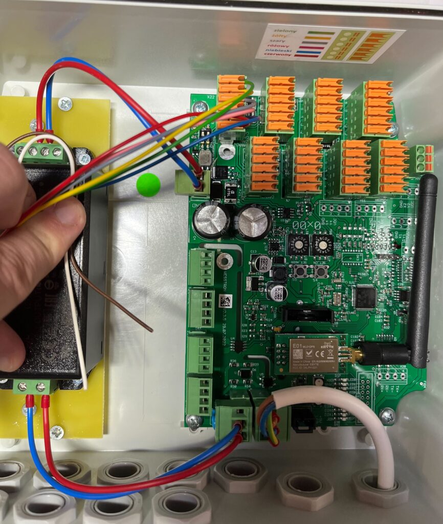
Insert the plug into the socket from dispenser number 1
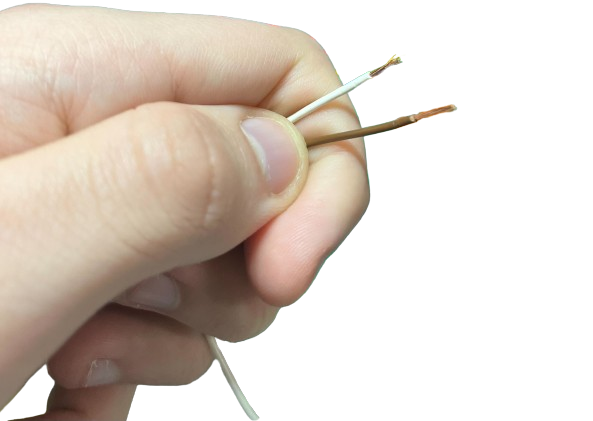
Hand holding the stripped ends of the white and brown wires after removing their insulation, ready for crimping.

Remove the insulation from the white and brown wires.
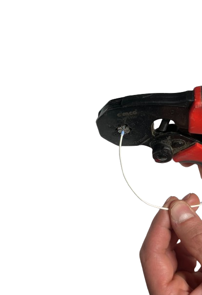
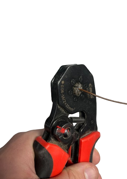
Crimping tool fitting a wire ferrule (collet) onto the stripped end of the white wire.

Apply and tighten the collet to the white wire.
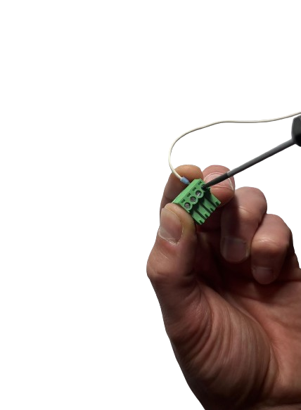
Screwdriver used to insert the white wire (neutral) into its terminal plug near the control board.

Apply and tighten the collet to the brown wire.
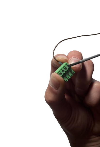
Screwdriver used to insert the brown wire (phase) into its terminal plug near the control board.

Remove the plug for connecting the white wire, unscrew the screw so that the wire can be inserted, then insert it and tighten the screw.
Screwdriver tightening the terminal screws on the dispenser 1 plug connector held in hand.

Remove the plug for connecting the brown wire, loosen the screw so that the wire can be inserted, then insert it and tighten the screw.
Hand inserting the plug with the white neutral wire into the DC power supply terminal inside the Connector case.

Tighten the terminals at the plug from dispenser number 1 with a screwdriver.
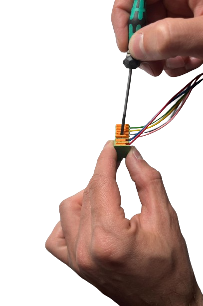
Hand inserting the plug with the brown phase wire into the DC power supply terminal inside the Connector case.

Insert the plug with the white wire (neutral wire)
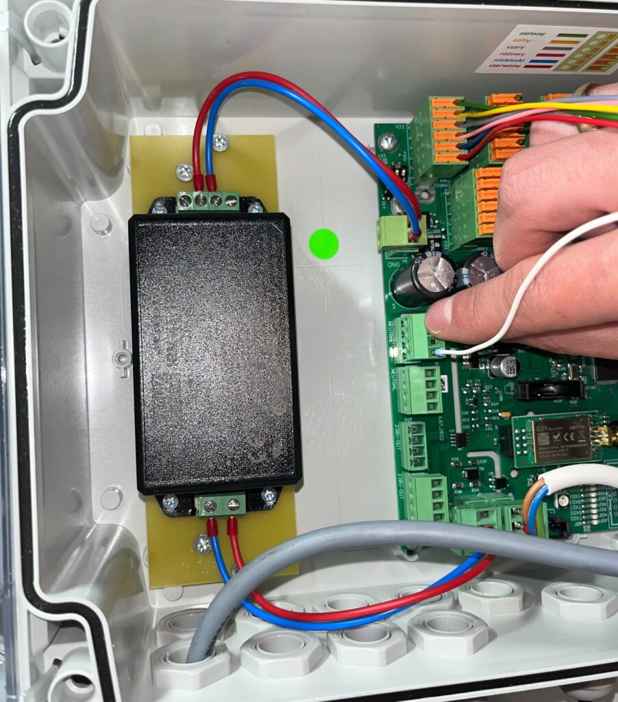
Open Connector case showing dispenser 1 wiring complete, with the color-coded plug connected to the board while a hand finishes the neutral and phase wire connections at the power supply terminal.

Insert the plug with the brown wire (phase wire)
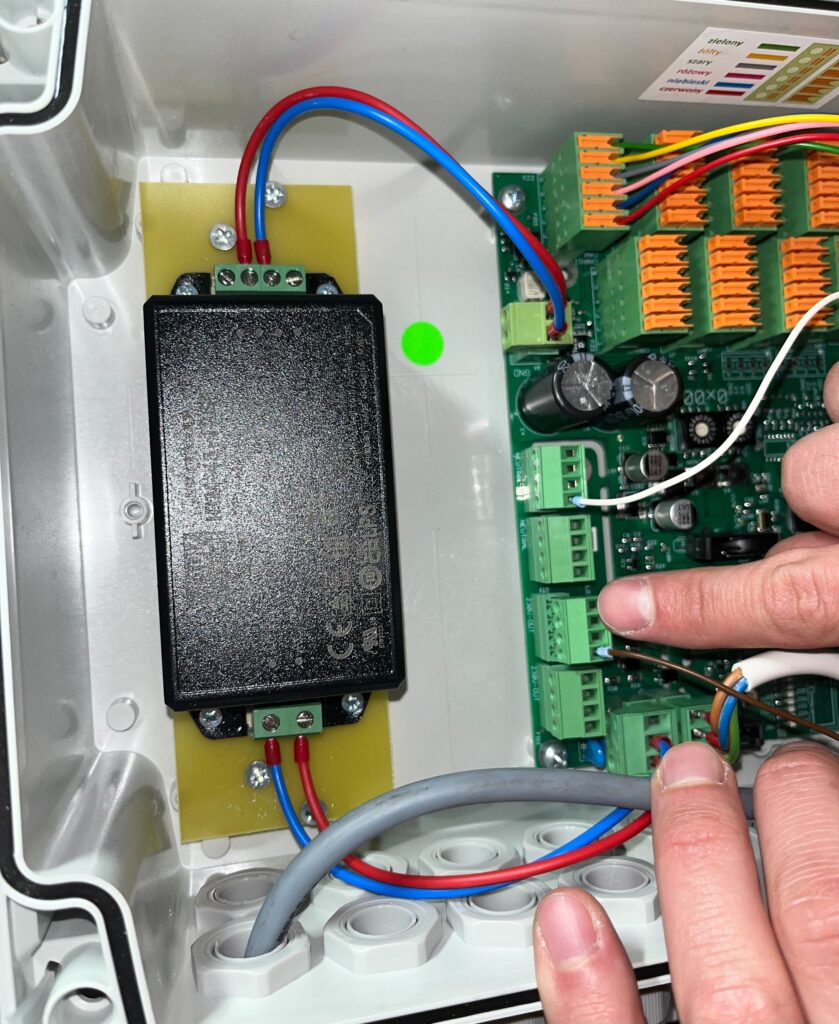
Open Connector case after dispenser 2 is wired, with two sets of color-coded wires now connected to the terminal blocks.

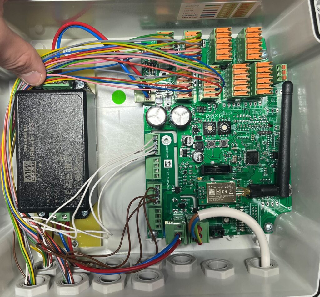
After connecting dispenser number 1 Connector should look as shown below.
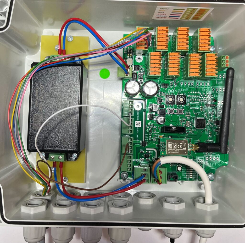
Open Connector case after dispenser 3 is wired, showing three bundles of color-coded wires connected to the board.

Follow the steps from Connecting a single dispenser to connect the other dispensers.

Connect dispenser number 2
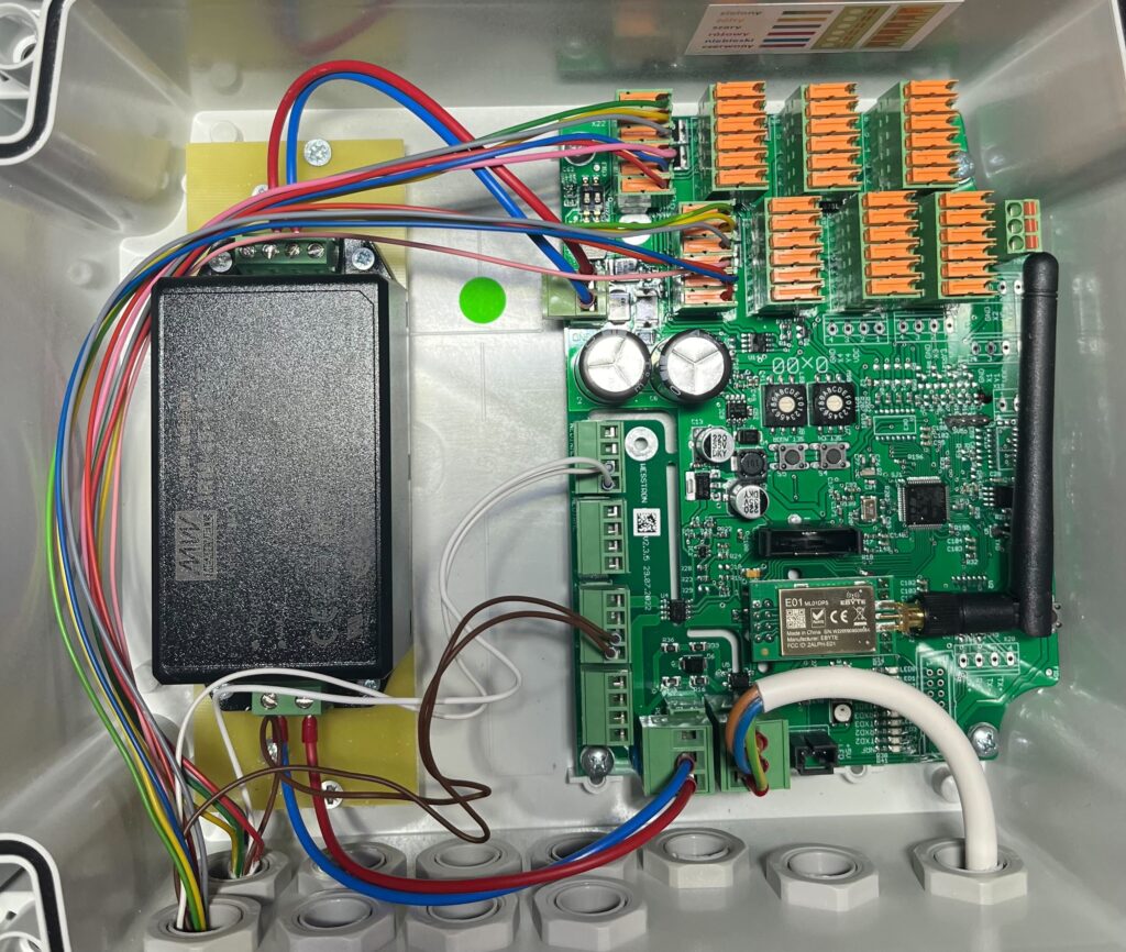
Open Connector case after dispenser 4 is wired, with four sets of color-coded wires routed to the terminal blocks.

Connect dispenser number 3

Open Connector case after dispenser 5 is wired, showing an increasing bundle of color-coded wires connected to the board.

Connect dispenser number 4

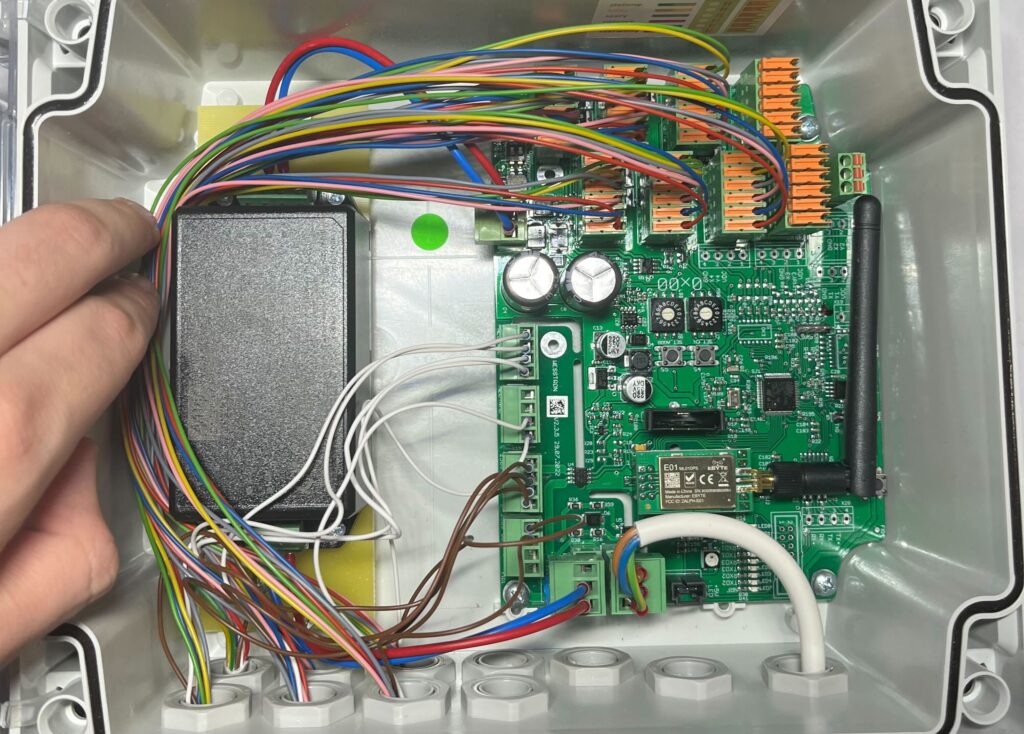
Hand routing wires in the Connector case after dispenser 6 is wired, with six bundles of color-coded wires now connected.

Connect dispenser number 5

Open Connector case after dispenser 7 is wired, showing a dense bundle of color-coded wires connected to the terminal blocks.

Connect dispenser number 6

Hand reaching into the Connector case after dispenser 8 is wired, showing all eight sets of color-coded wires connected to the board.

Connect dispenser number 7

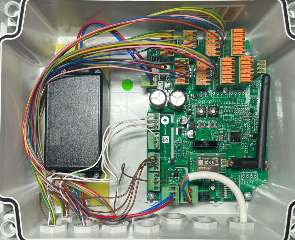
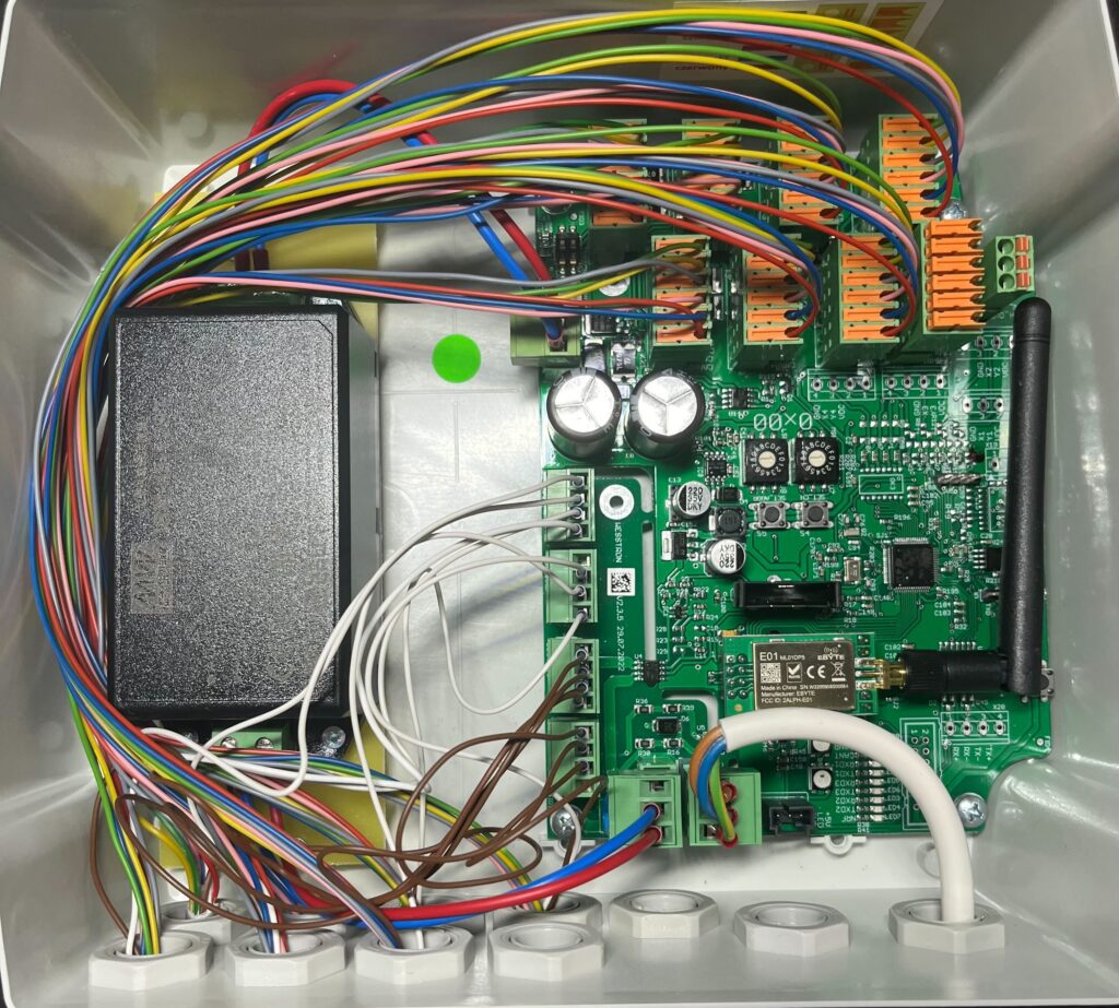
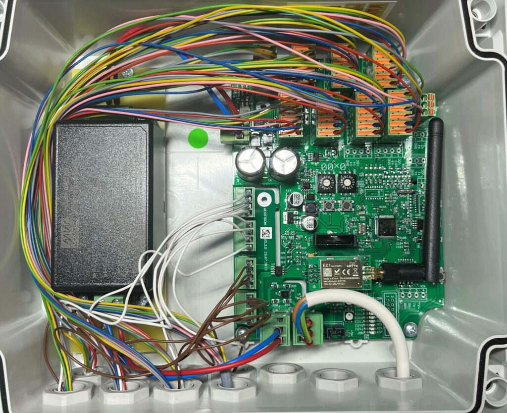
Open Connector case with all eight dispensers wired, showing the full bundle of color-coded wires connected to the terminal blocks before closing the case.

Connect dispenser number 8

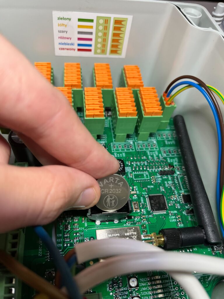
Hand inserting a CR2032 coin battery into its holder on the Connector control board.

Insert the battery into the Connector
Hand holding the end of a stripped communication cable wire before crimping, as part of preparing the CAN cable between Connector and Connector Extension.

Wiring CAN communication to Connector Extension

If you are connecting Connector to Connector Extension prepare a 3 x 0.75 mm2 cable. This is a communication cable that allows data exchange between the Connector and Connector Extension.

Close-up of a single wire with its insulation stripped, ready for fitting a collet before connecting to Connector Extension.

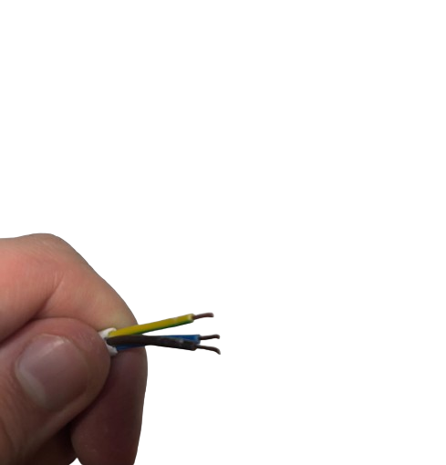
Remove the insulation from the cable, then strip the insulation from each wire.
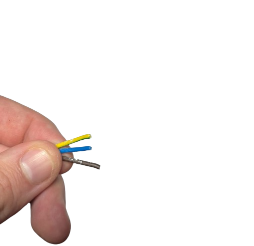
Hand holding a 3-core cable with the yellow and blue wires stripped and exposed, in the process of preparing the CAN communication cable.
Hand holding a 3-core cable with yellow and brown wires stripped and exposed, continuing preparation of the CAN communication cable.

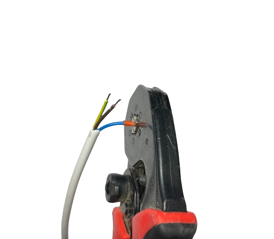
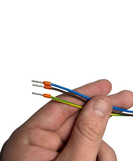
Fit and tighten the collets

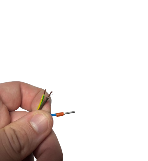
Hand holding three stripped wire ends (brown, yellow-green, and one with an orange collet fitted) from the CAN communication cable.
Crimping tool fitting a collet onto the stripped ends of the CAN communication cable's white, brown and blue wires.
Hand holding three wires (blue, brown, green) with orange collets crimped onto their stripped ends, ready for insertion into the CAN communication plug.

Remove the plug from CAN communication and insert the wires into it, when inserting them slightly press them with a screwdriver.
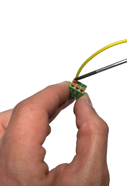
Hand inserting the yellow wire with a screwdriver into the green CAN communication plug connector.

Connect the plug from CAN communication
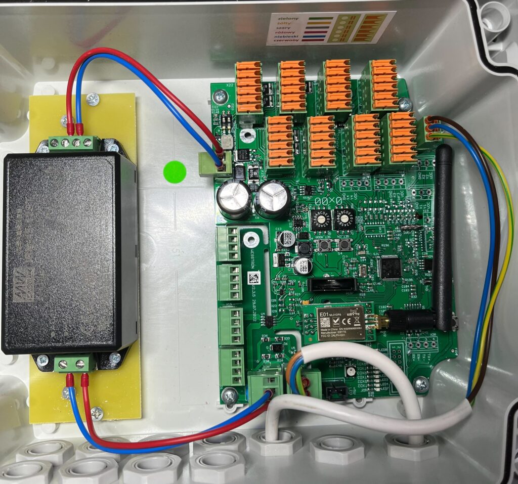
Open Connector case showing the CAN communication plug connected to the control board with blue, red, yellow and brown wires routed to it.

Connect Connector to Connector Extension with CAN cable
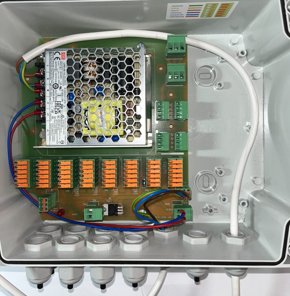
Open Connector Extension case showing its power supply module, orange terminal blocks and green connectors, with the CAN cable's colored wires already routed to the board.

The correct CAN communication connection is shown below.
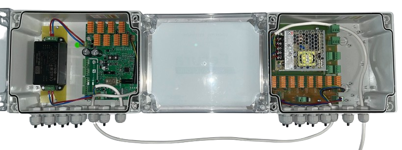
Both the Connector and Connector Extension housings placed side by side with their lids open, connected underneath by a white cable, showing the completed CAN wiring between the two devices.

Connecting dispensers main power to Connector Extension

If you are connecting the Connector to the Connector Extension prepare a 3 x 1.5 mm2 cable. This is the cable that powers the motors in the dispensers connected to the Connector Extension.

Remove the insulation from the cable, then strip the insulation from each wire.
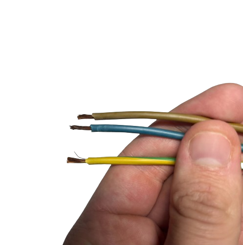
Hand holding three stripped wire ends (brown, blue, yellow-green) from the dispenser motor power cable, ready for crimping.

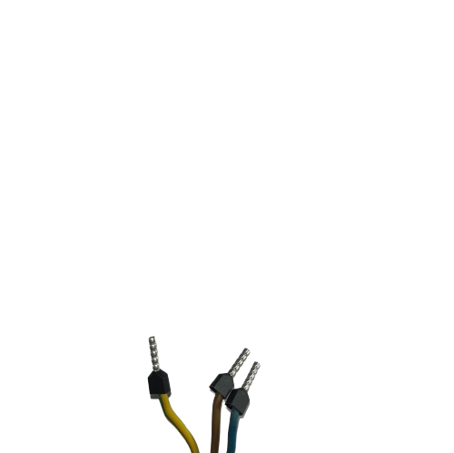
Install and tighten the collets.

Close-up of three wires (yellow-green, brown, blue) fitted with crimped collets on their stripped ends, ready to be inserted into a plug.

Insert the green-yellow (protective conductor) wire into the plug with the VDC power supply connected.
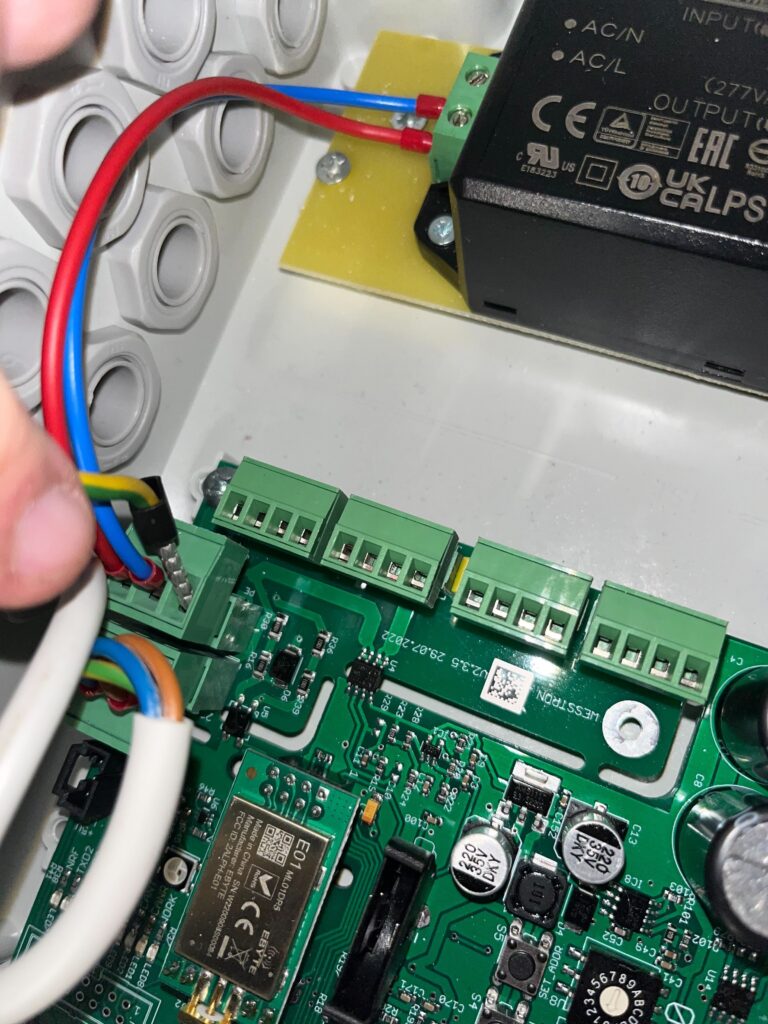
Hand inserting the green-yellow protective conductor wire into the plug connected to the VDC power supply inside the Connector case.

Remove the plug from the brown wires (phase wire) and connect the brown wire there.
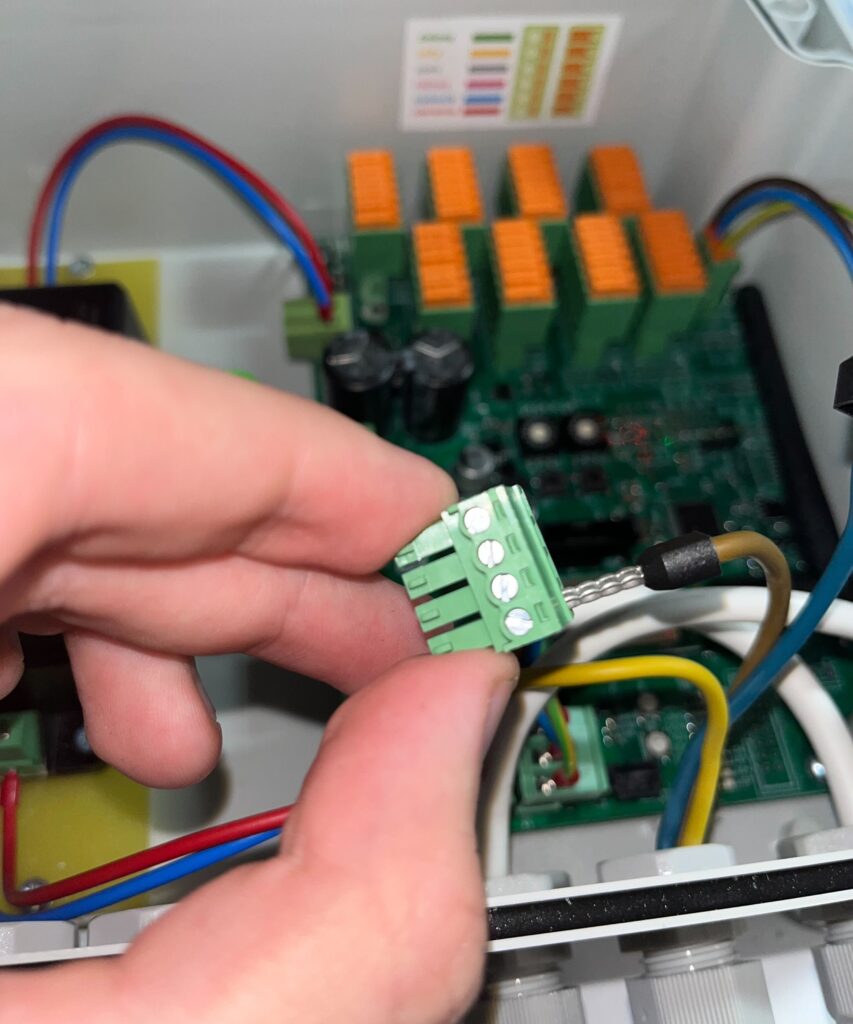
Hand holding a green terminal plug while inserting the brown phase wire, near the orange terminal blocks and color-coding label inside the Connector case.

Remove the plug from the white wires (neutral wire) and connect the blue wire there.
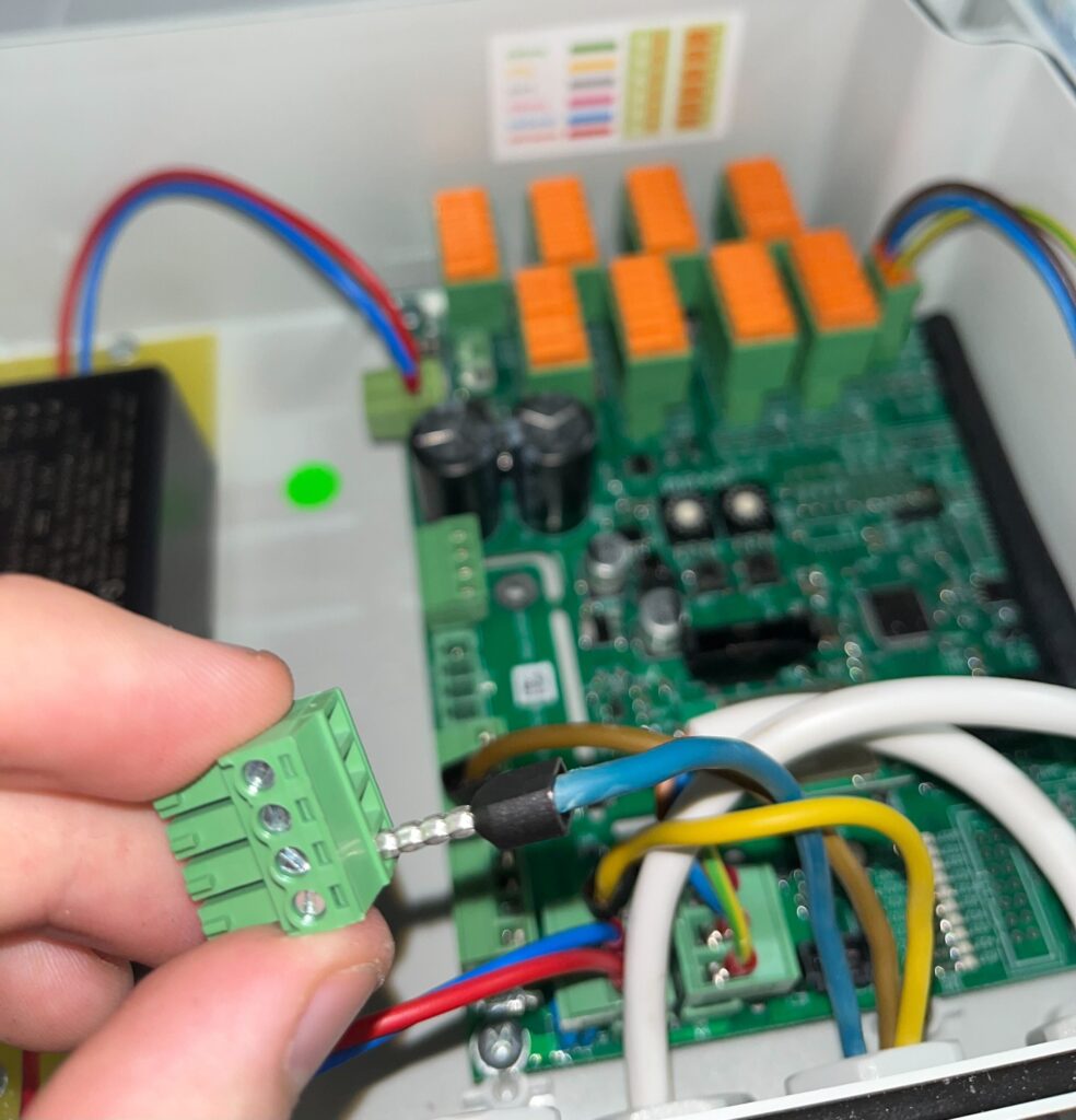
Open Connector case showing the dispenser motor power supply wiring connected to the DC power module and control board with red and blue wires.

A properly made connection in the Connector should look as shown below.
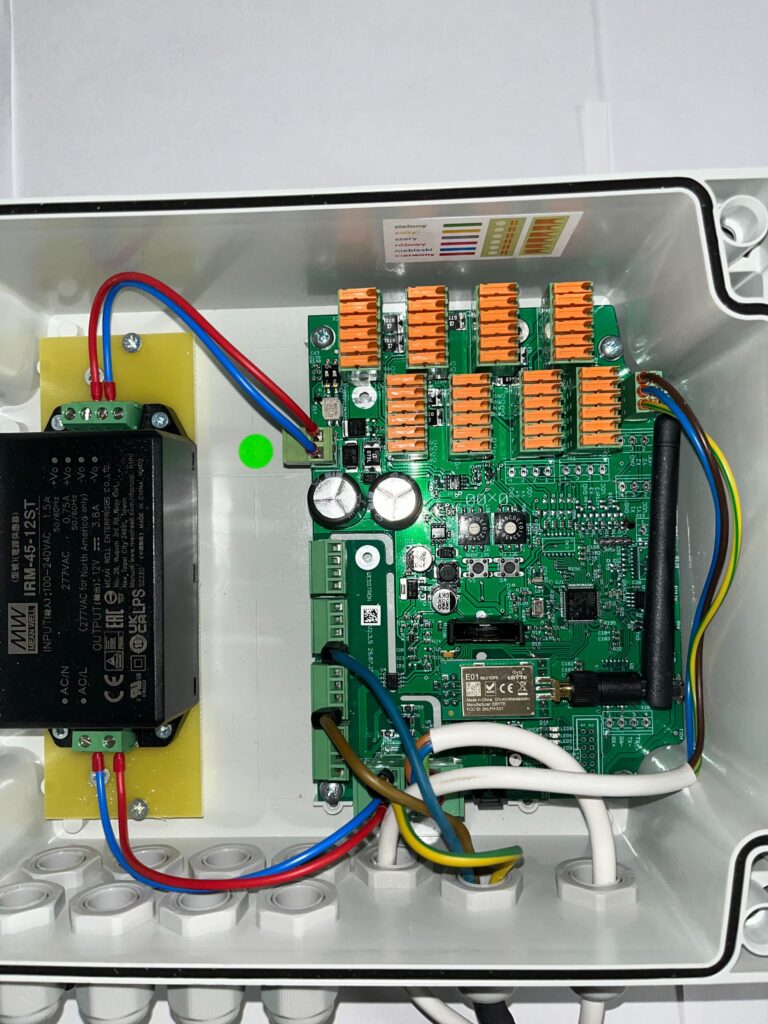
Open Connector Extension case showing its power supply board with orange terminal blocks and green connectors, ready for the dispenser motor power plug.

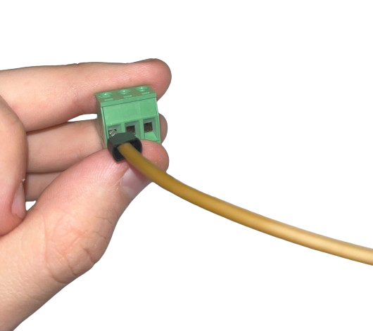
From the Connector Extension, remove the plug from the dispenser motor power supply and connect the brown wire (phase wire)
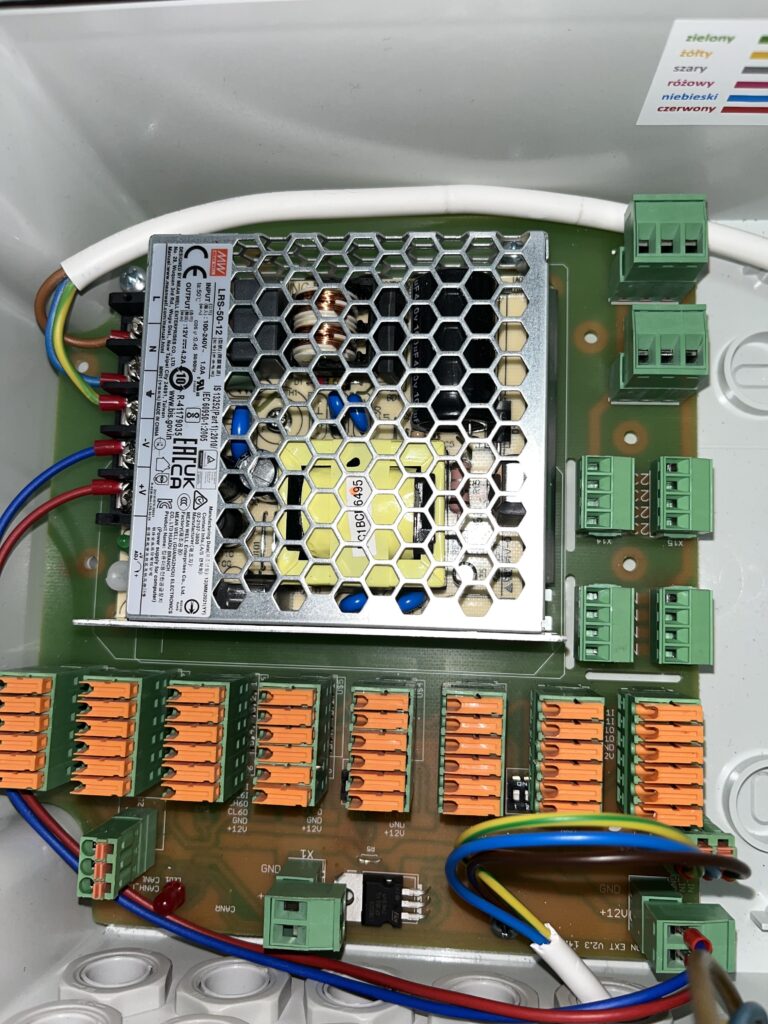
Open Connector Extension case power supply board with orange terminal blocks, showing the layout used for wiring dispenser motor power and CAN communication.
Hand holding a green terminal plug with the brown phase wire inserted, removed from the Connector Extension's dispenser motor power supply socket.

Connect the blue wire (neutral wire)
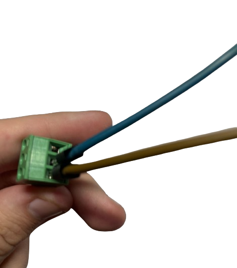
Hand holding the green terminal plug with the blue neutral wire now also connected, for the Connector Extension dispenser motor power supply.

Connect the green-yellow wire (protective wire)
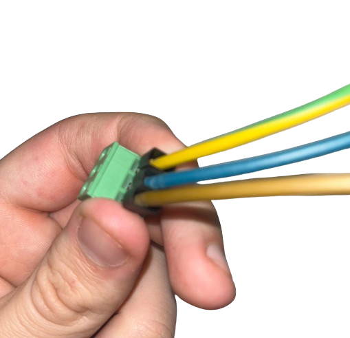
Hand holding the green terminal plug with all three wires (yellow-green, blue, brown) connected, ready to plug into the Connector Extension's dispenser motor power supply socket.

Connect the plug from the dispenser motor power supply
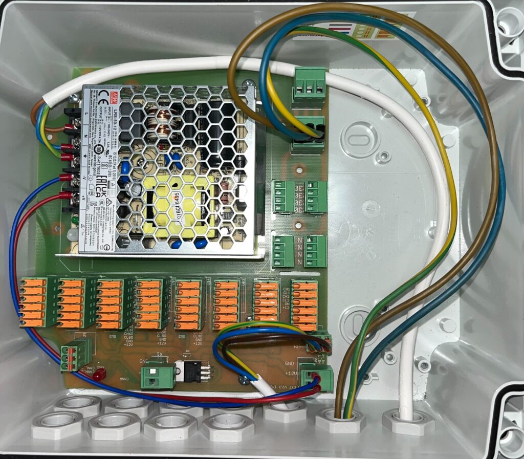
Open Connector Extension case showing the completed dispenser motor power supply wiring with brown, yellow-green and blue wires connected to the power board.

After connecting the power supply to the dispenser motors and CAN communication between the Connector and Connector Extension, the devices should look as shown below.
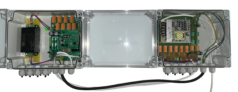
Connector and Connector Extension housings shown side by side with lids open, connected by black and white cables, after power supply and CAN communication wiring is complete.

Connector Extension

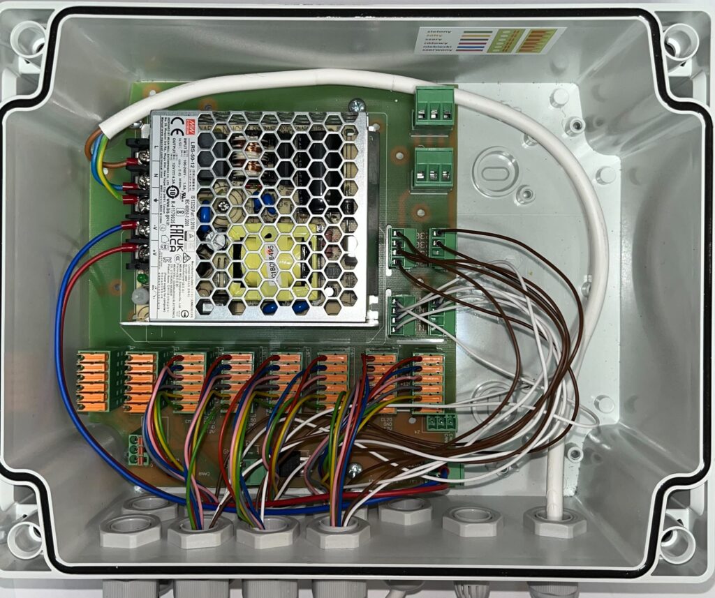
Connector Extension in the factory state has the main power supply and DC power supply connected and is prepared for connecting dispensers.
Correct operation of Connector Extension requires connection of CAN communication and power supply of dispenser motors directly to Connector. It is described in this article.
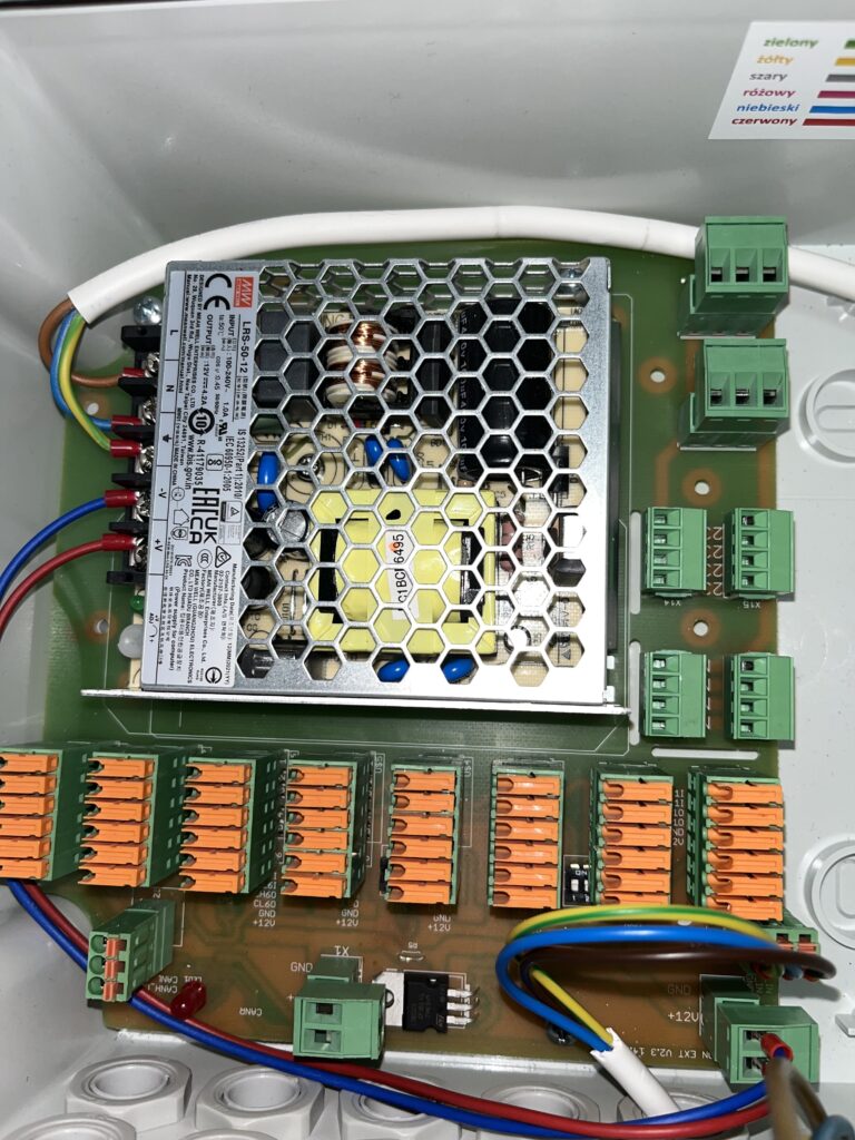
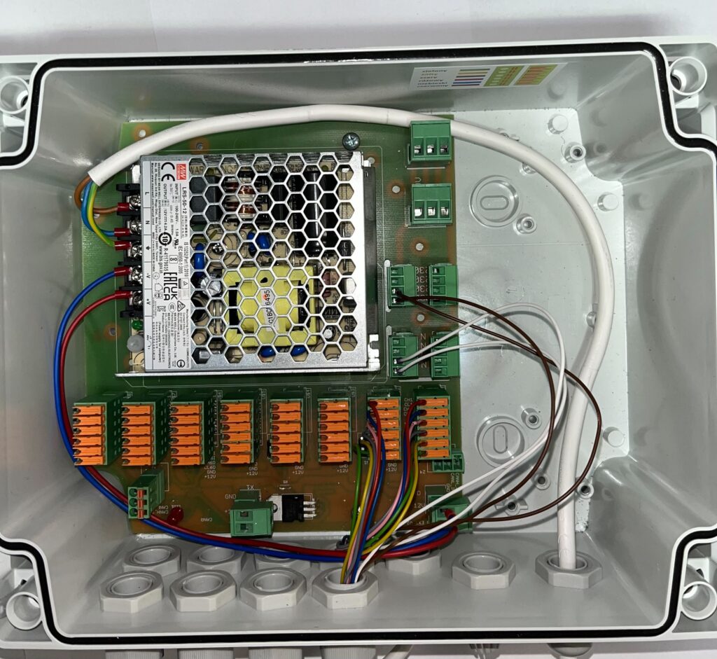
Open Connector Extension case showing its power supply board, orange terminal blocks and brown/white wires routed for the first dispenser connection.

Connect dispenser number 1

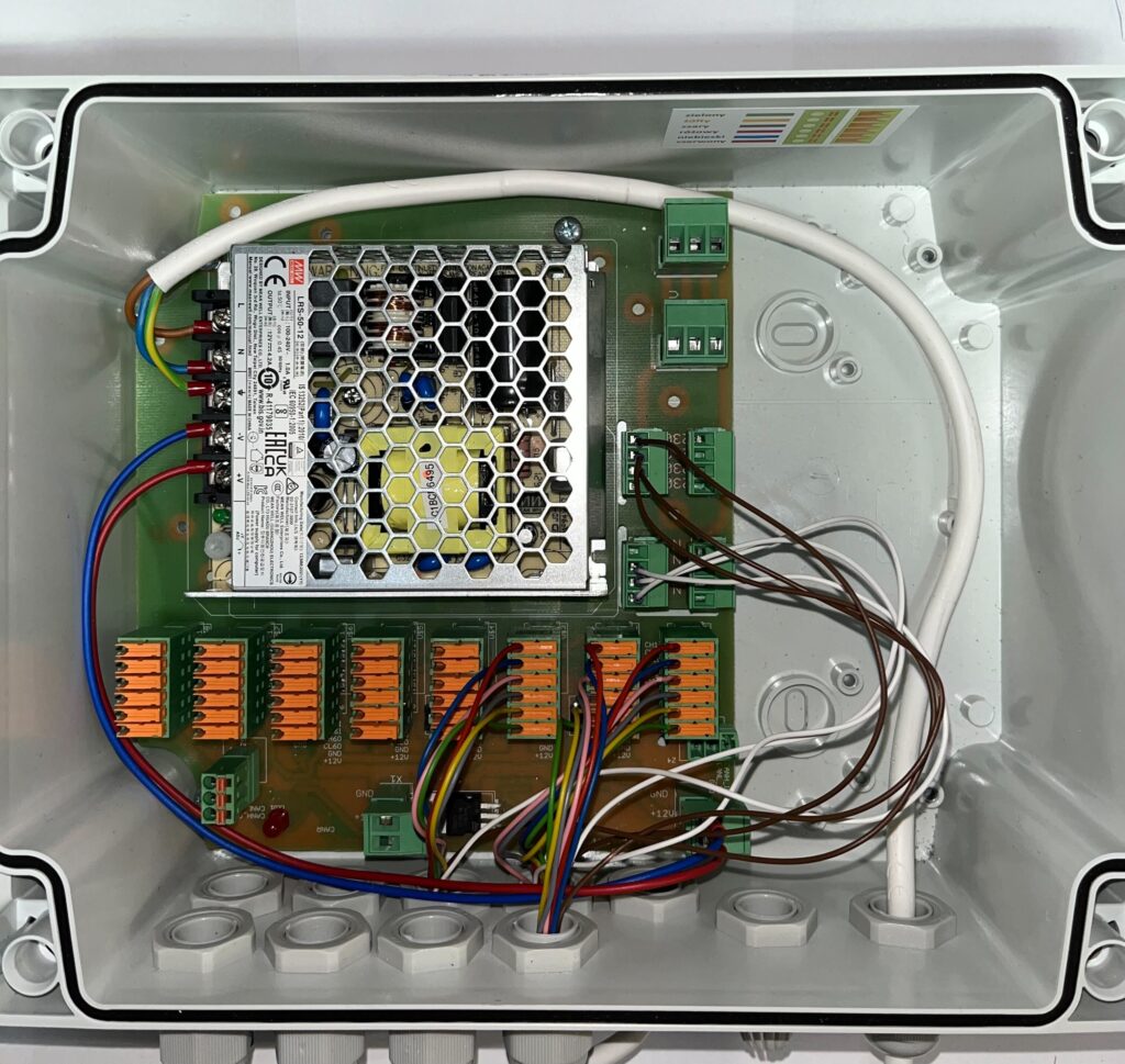
Open Connector Extension case after dispenser 2 is wired, showing an additional bundle of color-coded wires connected to the terminal blocks.

Connect dispenser number 2

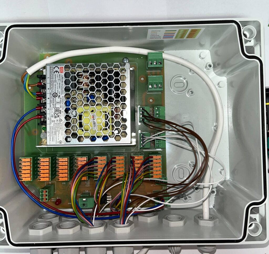
Open Connector Extension case after dispenser 3 is wired, with three sets of color-coded wires now connected to the board.

Connect dispenser number 3

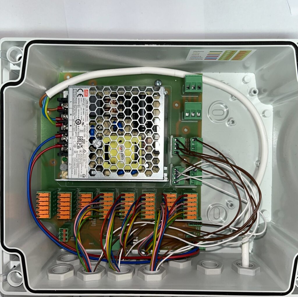
Open Connector Extension case after dispenser 4 is wired, showing four bundles of color-coded wires connected to the terminal blocks.

Connect dispenser number 4

Open Connector Extension case after dispenser 5 is wired, with an increasing bundle of color-coded wires routed to the board.

Connect dispenser number 5

Open Connector Extension case after dispenser 6 is wired, showing six sets of color-coded wires connected to the terminal blocks.

Connect dispenser number 6

Open Connector Extension case after dispenser 7 is wired, showing the full bundle of color-coded wires connected to all terminal blocks.

Connect dispenser number 7

Open Connector Extension case with all seven dispensers wired, showing the complete set of color-coded wire bundles connected to the power board.

The end result

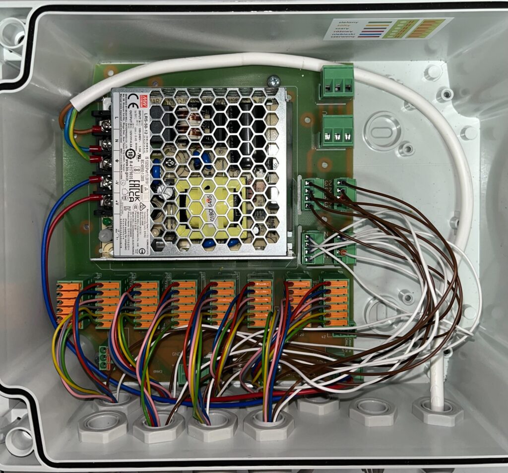
After connecting all the dispensers, CAN communication and powering the motors in the dispensers, the complete setup looks like the picture below.
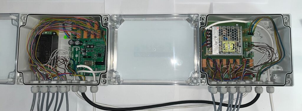
Connector and Connector Extension housings shown side by side with lids open, fully wired with all dispensers, CAN communication and power connections completed, connected to each other by cables.
Updated on 2026-07-22
Was this article helpful?

Related Articles

Need Support?
Can't find the answer you're looking for?
Contact Support

Leave a Comment