Bridge RS422
- Connect main power supply [1] (115VAC or 230VAC) to the DC DIN rail power supply
- Connect RS422 communication cable [2] to Cloud Box
Signals description from left: A, B, Z, Y - Connect NRF antennas [3] (optional)
NRF interfaces a (left), b (central), c (right)
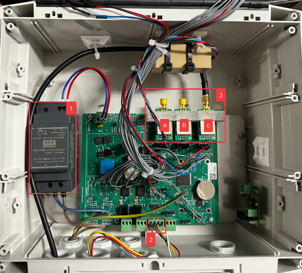
| NO. | Description |
| 1 | Main power supply 24VDC (input power supply 115VAC or 230VAC) |
| 2 | RS422 (wired connection to Cloud Box) Signals description from left: A, B, Z, Y |
| 3 | NRF antennas interfaces a (left), b (central), c (right) |
Bridge ETH
- Connect main power supply [1] (115VAC or 230VAC) to the DC DIN rail power supply
- Connect LAN cable [2].
- Connect NRF antennas [3] (optional)
NRF interfaces a (left), b (central), c (right)
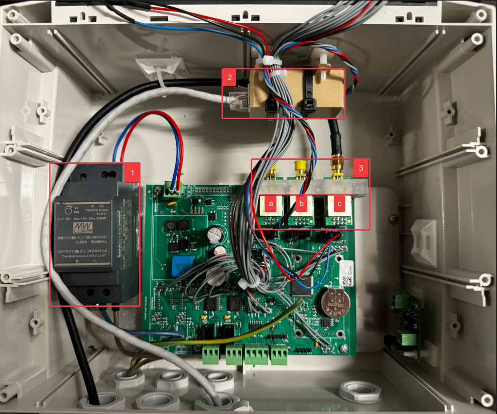
| NO. | Description |
| 1 | Main power supply 24VDC (input power supply 115VAC or 230VAC) |
| 2 | LAN (wired Internet network connection) |
| 3 | NRF antennas interfaces a (left), b (central), c (right) |