1. Home
  2. Devices
  3. Micrclimate SK4
  4. How to add a climate controller to an application?

How to add a climate controller to an application?

This tutorial will describe what steps need to be taken, in order to add the SK-3 and SK-4 climate controller to the application.

Devices tab

After logging in, go to the “Settings” tab.
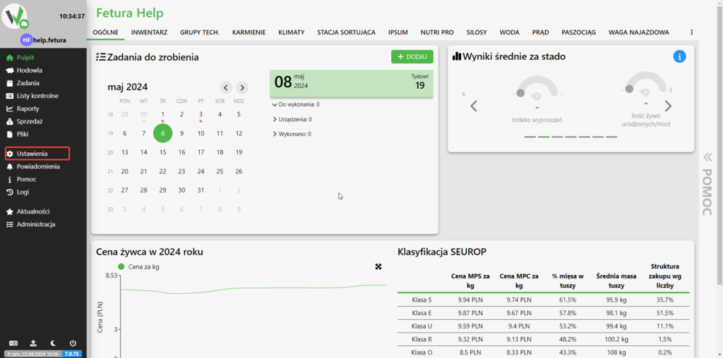
Fetura CLOUD desktop dashboard with the top navigation tabs and the "Settings" item in the left sidebar highlighted in red.

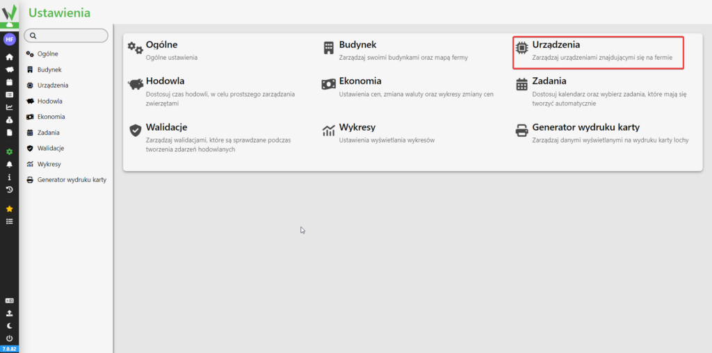
Then go to the “Devices” tab.

Settings screen tiles with the "Devices" tile highlighted in red.

Then go to the “Device Management” tab.
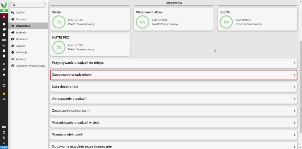
Devices screen with device-type tiles (Silos, Weaner Scales, IPSUM, NUTRI PRO) and the "Manage devices" option highlighted in red.

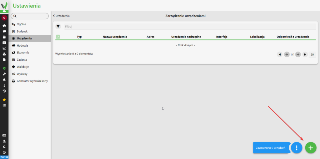
Then click the highlighted button

Manage Devices screen with an empty device list and a red arrow pointing to the "+" button in the bottom-right corner, used to add a new device.

Adding a climate controller

If you want to add SK-3 from the available options, select [1], otherwise select [2].
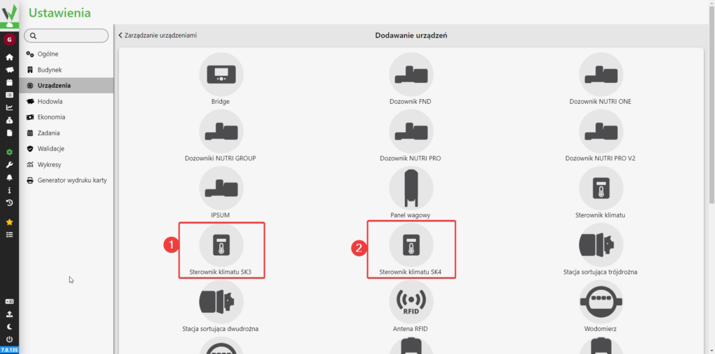
Add Devices screen (Dodawanie urządzeń), reached from Device Management, with 'Sterownik klimatu SK3' marked 1 and 'Sterownik klimatu SK4' marked 2 highlighted in red for selection. The device-type tiles visible on this screen are, in order: Bridge, Dozownik FND, Dozownik NUTRI ONE, Dozowniki NUTRI GROUP, Dozownik NUTRI PRO, Dozownik NUTRI PRO V2, IPSUM, Panel wagowy, Sterownik klimatu, Sterownik klimatu SK3, Sterownik klimatu SK4, Stacja sortująca trójdrożna, Stacja sortująca dwudrożna, Antena RFID, Wodomierz. The grid continues below the visible area.

Enter the name you want the climate controller to have [1], enter the address of the controller [2], enter which Bridge it is to be connected to [3], select the hardware version of the controller [4], select whether the controller is to be included in the analysis of breeding results [5], optionally enter a number so that the controllers can be distinguished in the climate tab [6], select what type of mats are connected to the controller [7], in the case of electric mats, enter how many mats are connected to the controller [8].
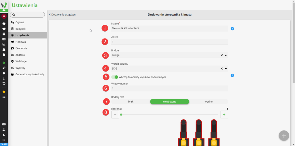
Add Climate Controller form (Dodawanie sterownika klimatu) with red numbered circles 1 to 8 marking: 1 Nazwa, the controller name, here 'Sterownik Klimatu SK-3'; 2 Adres, the address, here 1; 3 Bridge, a dropdown; 4 Wersja sprzętu, the hardware version, here SK-3; 5 the toggle 'Wliczaj do analizy wyników hodowlanych', include in breeding results analysis, switched on; 6 Własny numer, own number, here 1; 7 Rodzaj mat, mat type, offered as three buttons brak (none), elektryczne (electric) and wodne (water) with elektryczne selected; 8 Ilość mat, number of mats, a slider set to 1. Below the form the climate controller board diagram begins.

Then select which interface the controller is connected to by clicking on the corresponding connector [1][2].
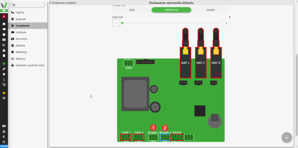
Climate controller board diagram shown while adding the device; you choose the interface the controller is wired to by clicking the matching connector, 1 pointing to RS485-1 and 2 pointing to RS485-2, which is framed in blue here. The diagram labels every connector on the board: the mains block marked 230V with pins PE, N, L; CAN-1 with pins L, GND, H; CAN-2 with pins L, GND, H; RS485-1 with pins B, GND, A; RS485-2 with pins B, GND, A; RS422 with pins Rx+, Rx-, Tx-, Tx+; and one further unlabelled three-pin block on the right. Three radio modules with antennas are drawn along the top and marked NRF L, NRF C and NRF R. Above the diagram are the settings 'Rodzaj mat' with buttons brak, elektryczne, wodne, and the 'Ilość mat' slider.

In the last step, click the highlighted button to add the driver to the application.
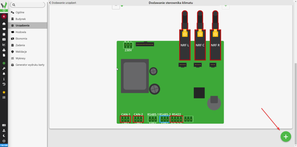
Climate controller board diagram in the final step of adding the device, with a red arrow pointing to the green plus button in the bottom-right corner that adds the controller to the application. The diagram labels the connectors as follows: the mains block marked 230V with pins PE, N, L; CAN-1 with pins L, GND, H; CAN-2 with pins L, GND, H; RS485-1 with pins B, GND, A; RS485-2 with pins B, GND, A; RS422 with pins Rx+, Rx-, Tx-, Tx+; and one further unlabelled three-pin block on the right. CAN-1, CAN-2 and RS422 are framed in red and RS485-2 is framed in blue. Three antenna modules along the top are marked NRF L, NRF C and NRF R.

Next steps

How do I configure a newly added climate controller?

How to create a climate curve?

How to connect the SK-3 climate controller?

Updated on 2026-07-28
Was this article helpful?

Related Articles

Need Support?
Can't find the answer you're looking for?
Contact Support

Leave a Comment