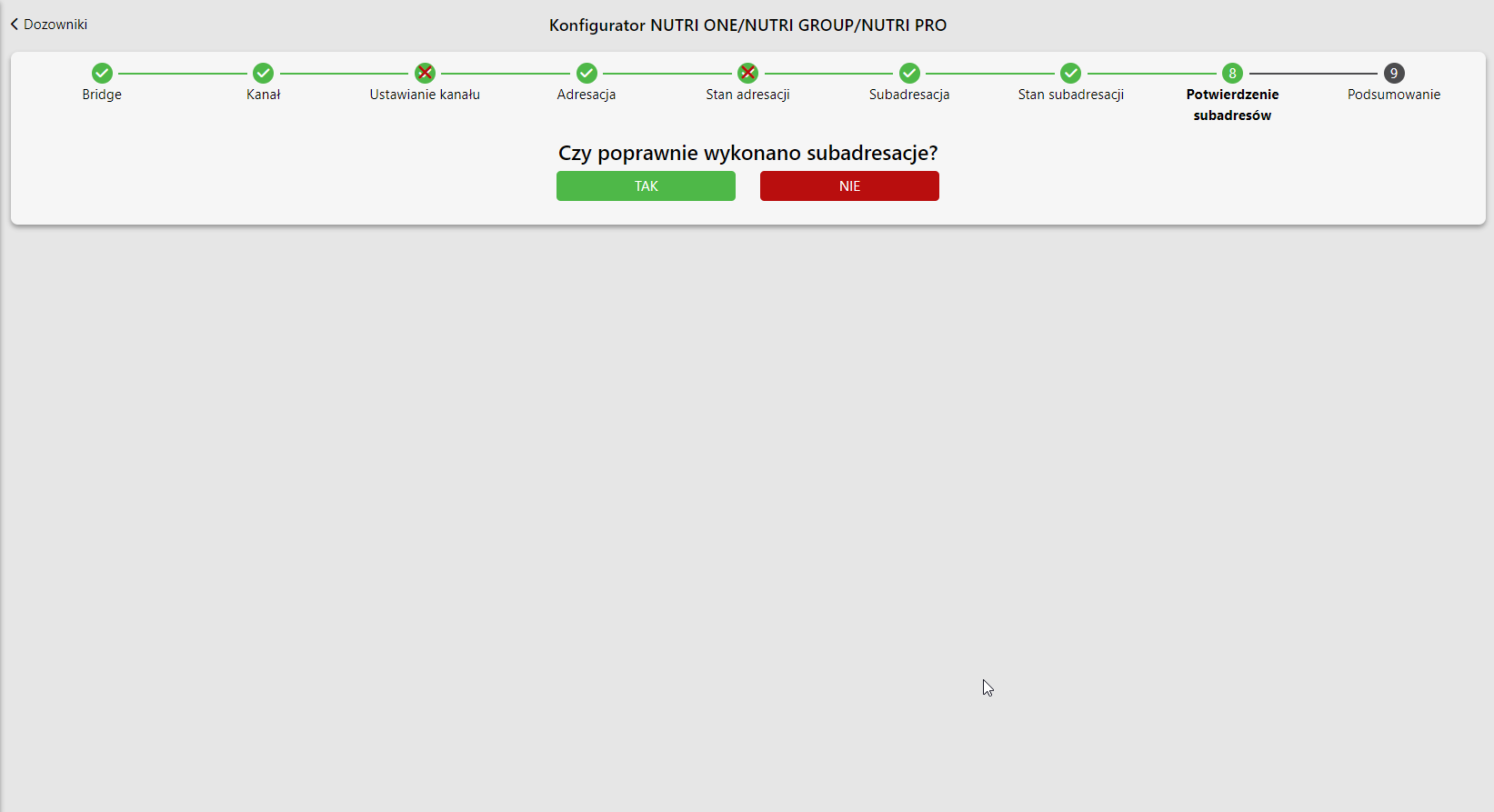
- Description of Nutri GROUP dispenser configuration in the application
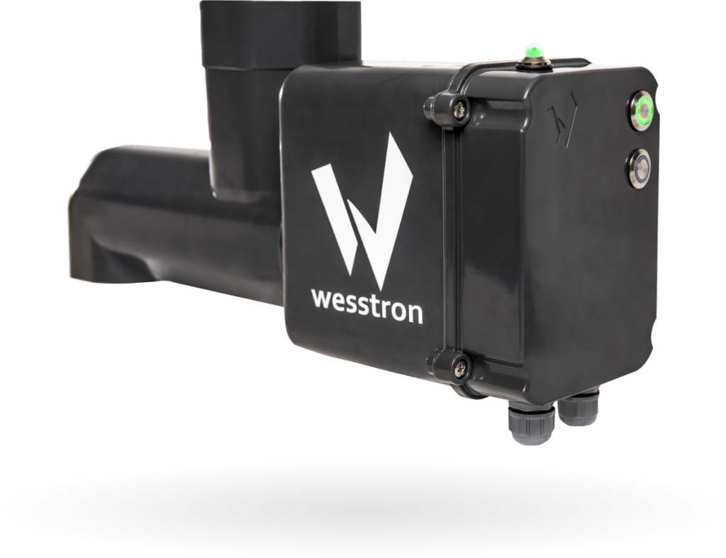
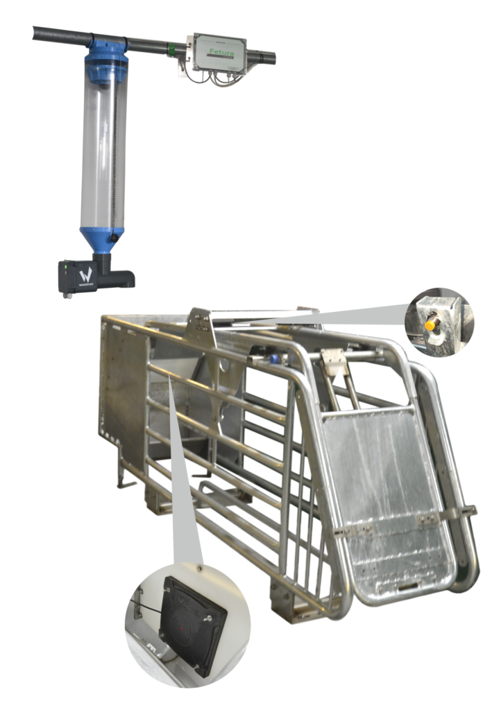
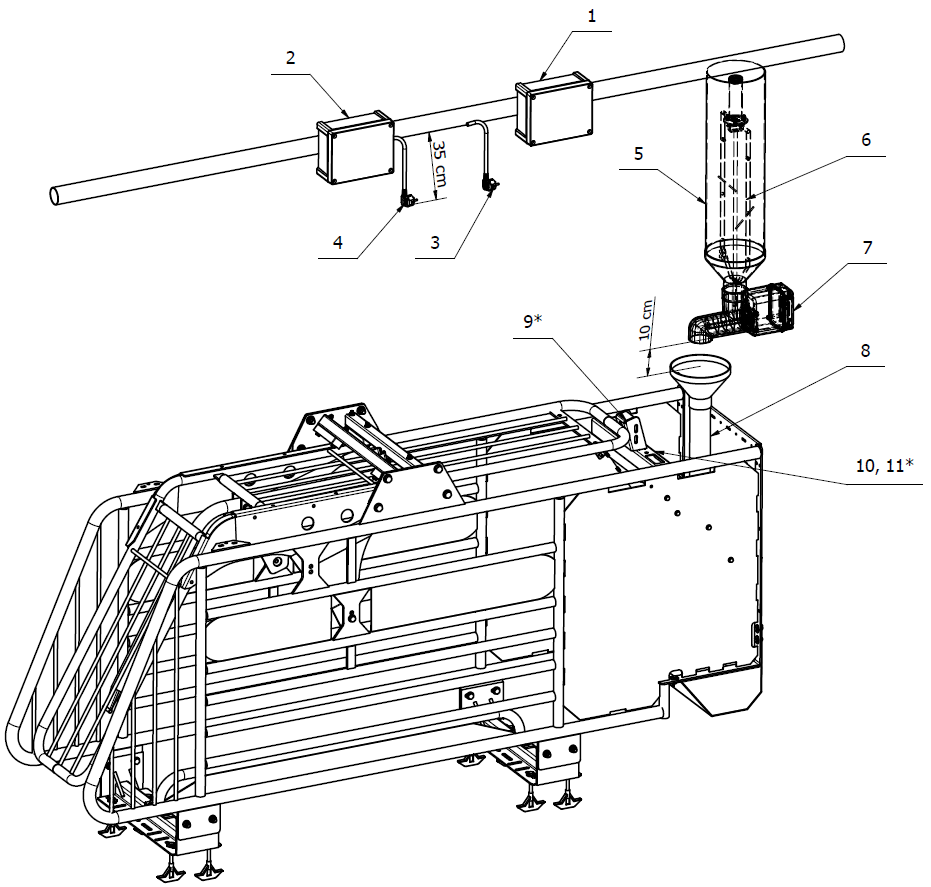
| Number | Description |
| 1 | Connector or Connector Extension (type of device depends on the technological design) |
| 2 | Power Box (optional) |
| 3 | YDY 3 x 1.5mm2 cable terminated with a hermetic socket |
| 4 | YDY 3 x 1.5mm2 cable terminated with a hermetic socket (optional) |
| 5 | Volumetric dispenser |
| 6 | Mixer (optional |
| 7 | Nutri GROUP electronic dispenser |
| 8 | Drain pipe |
| 9 | Self-locking cage latching sensor (optional) |
| 10 | RFID antenna |
| 11 | Nutri GROUP adapter (optional) |
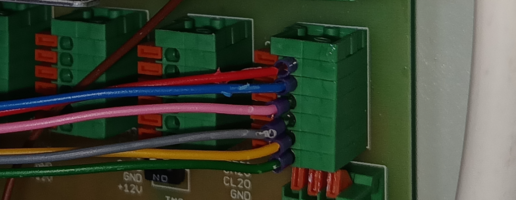
Nutri GROUP – wiring diagram for the Connector
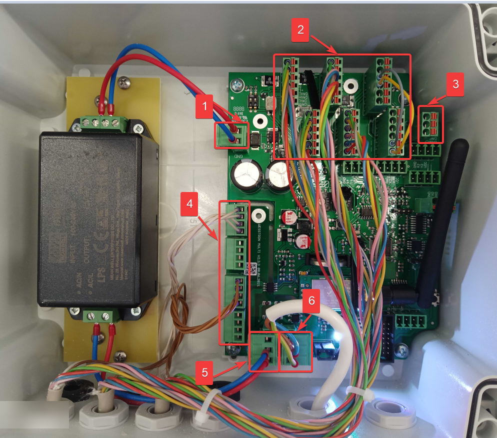
| Number | Description |
| 1 | Main power supply 12 VDC (from the top: +12 VDC, GND) |
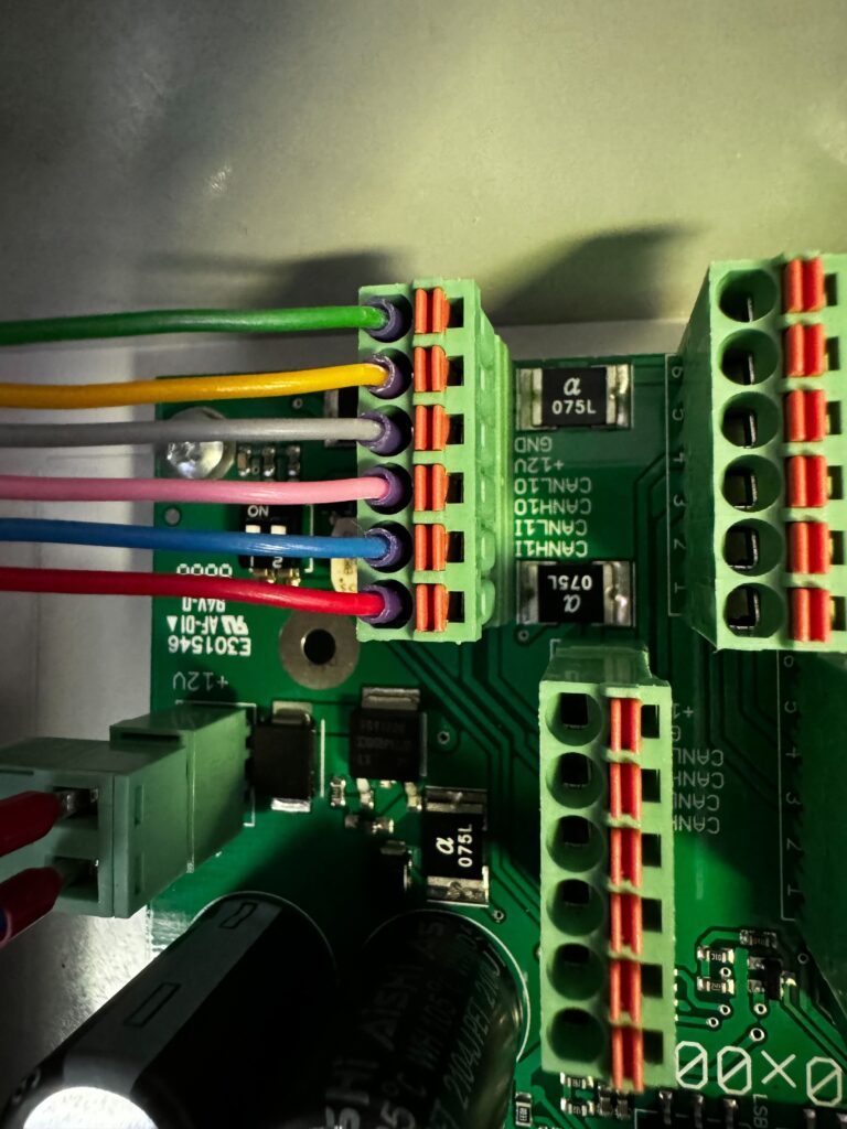
| 2 | Inputs for Nutri GROUP dispensers(max 8 pcs). (from top: +12VDC, GND, CANLxO, CANHxO, CANLxI, CANHxI) See Figure 5 |
| 3 | CAN communication output to Connector – Extension (from top: GND, CANL, CANH) |
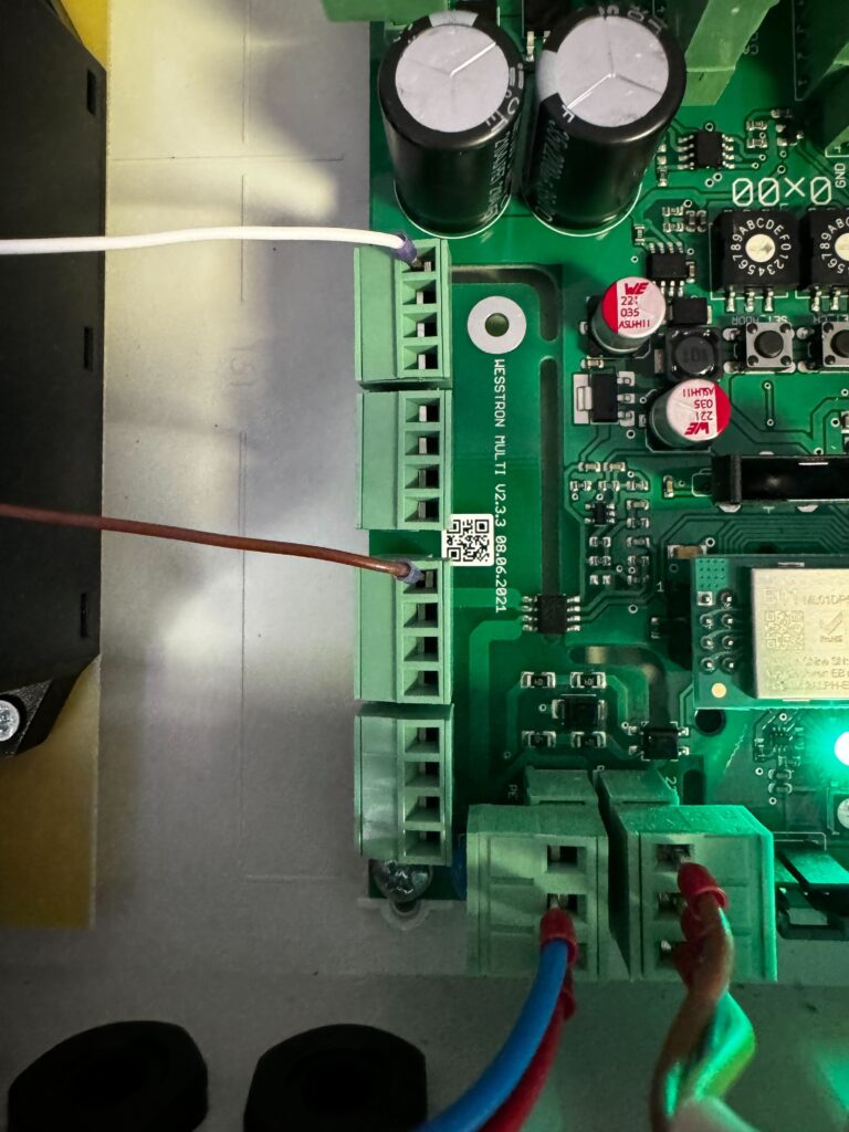
| 4 | 230 VAC power supply for Nutri GROUP dispensers (from the top: N, L) See Figure 6 |
| 5 | Output 230 VAC to built-in DC power supply (from top: PE, N, L) |
| 6 | Input 230 VAC – main power supply of the Connector (from the top: L, N, PE) |
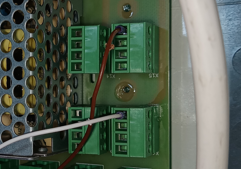
Nutri GROUP – wiring diagram for Extension Connector
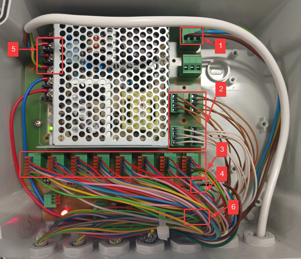
| Number | Description |
| 1 | 230 VAC input – serial connection from Connector (from left: L, N, PE) |
| 2 | 230 VAC power supply for Nutri ONE dispensers (from the top: N, L) See Figure 9 |
| 3 | Inputs for Nutri GROUP dispensers (max 8 pcs). (from bottom: +12VDC, GND, CANLxO, CANHxO, CANLxI, CANHxI) See Figure 8 |
| 4 | CAN communication input on Connector – Extension (from the left: GND, CANL, CANH) |
| 5 | 230 VAC input for built-in DC power supply (from the top: L, N, PE) |
| 6 | Main power supply 12 VDC (from the top: GND, +12 VDC) |
Nutri GROUP – connecting RFID antenna, mixer and cage latch sensor
Basic version
- Mount the wire from the RFID antenna to the self-locking cage structure
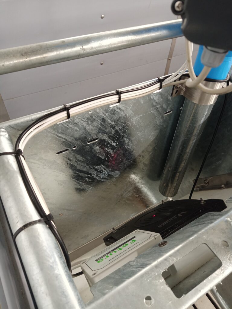
- Remove the 4 mounting screws and open the Nutri GROUP dispenser housing
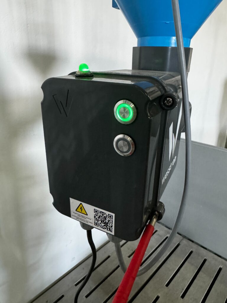
- Insert the cable from the antenna through the choke in the Nutri GROUP dispenser housing
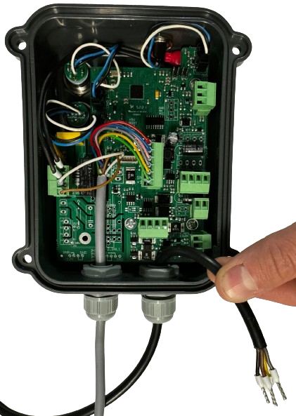
- Connect the wire from the RFID antenna to the plug
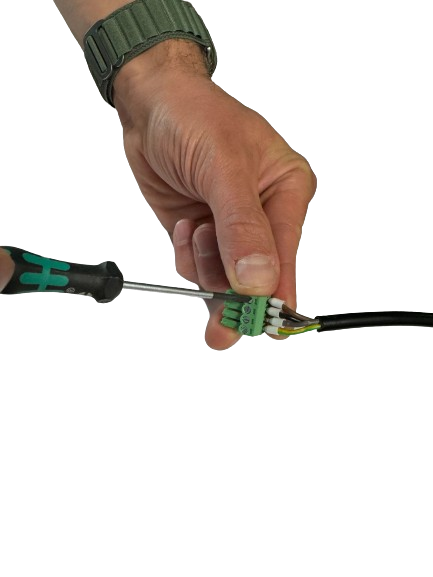
- Connect the plug to the socket from the RFID antenna
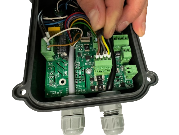
- Close the Nutri GROUP dispenser housing and tighten the 4 mounting screws

Enhanced version – Nutri GROUP adapter (RFID antenna)
- Mount the wire from the RFID antenna on the self-locking cage structure and feed it through the choke into the Nutri GROUP adapter

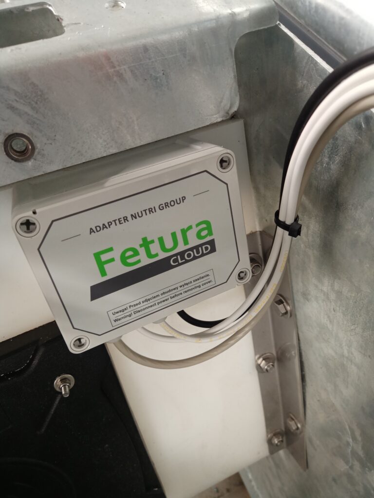
- Unscrew the 4 mounting screws, open the Nutri GROUP adapter housing and connect the plug to the socket from the RFID antenna
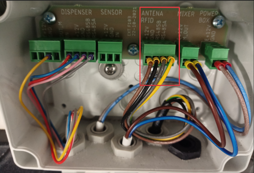
Enhanced version – Nutri GROUP adapter (stirrer)
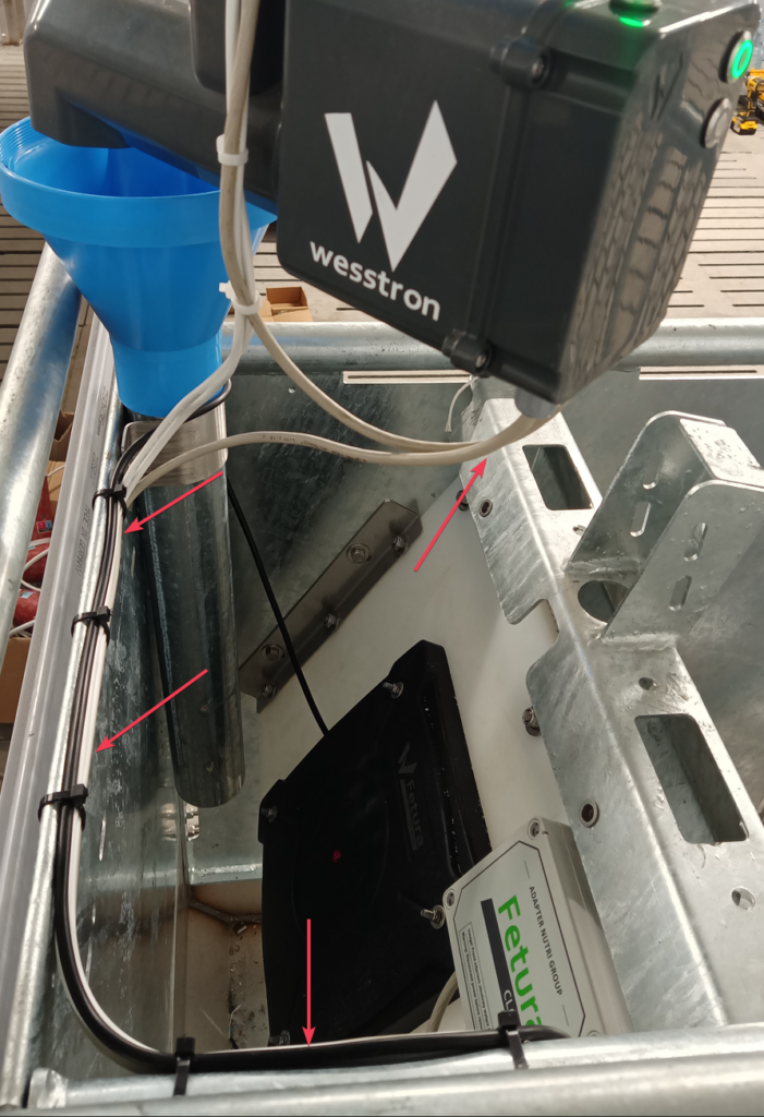
- Run the cable from the mixer along the volumetric dispenser, then mount it on the self-blocking cage structure and feed it through the choke into the Nutri GROUP adapter
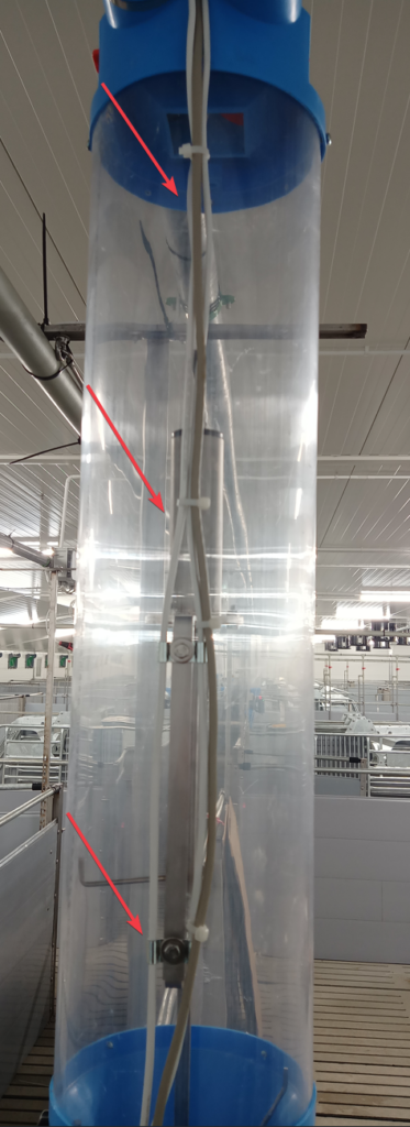
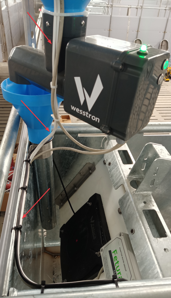

- Remove the 4 mounting screws, open the Nutri GROUP adapter housing and connect the plug to the socket from the mixer
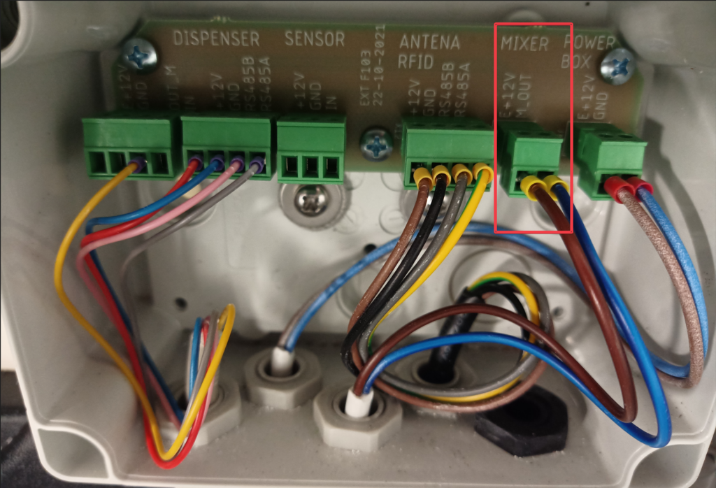
Enhanced version – Nutri GROUP adapter (latch sensor)
- Mount the cable from the latching sensor on the self-locking cage structure and feed it through the choke into the Nutri GROUP adapter

- Remove the 4 mounting screws, open the Nutri GROUP adapter housing and connect the plug to the socket from the snap sensor
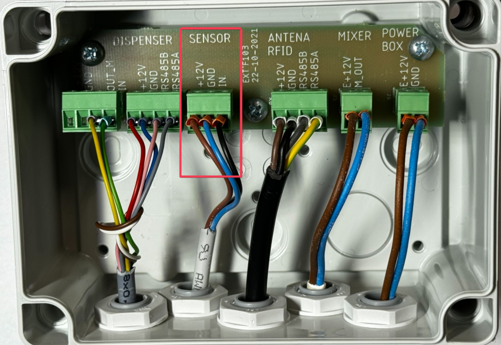
Extended version – connecting the adapter to the Nutri GROUP dispenser
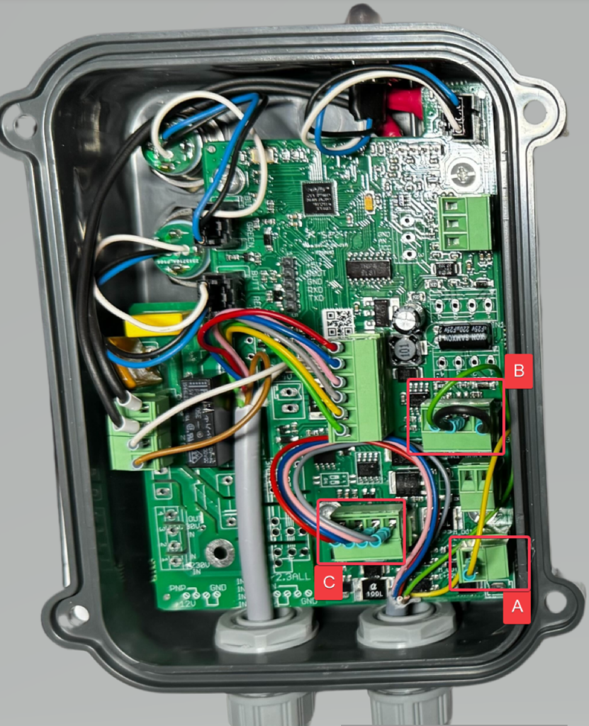
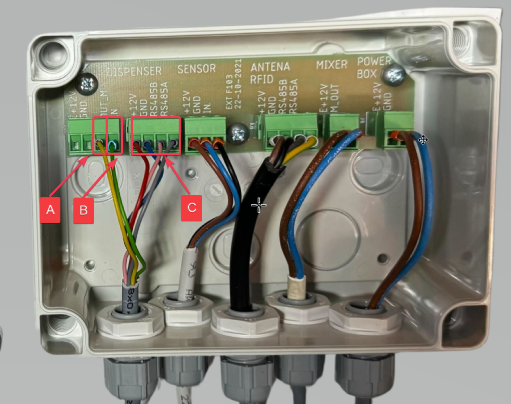
- Mount the cable from the Nutri GROUP adapter on the self-locking cage structure and feed it through the choke into the Nutri GROUP dispenser

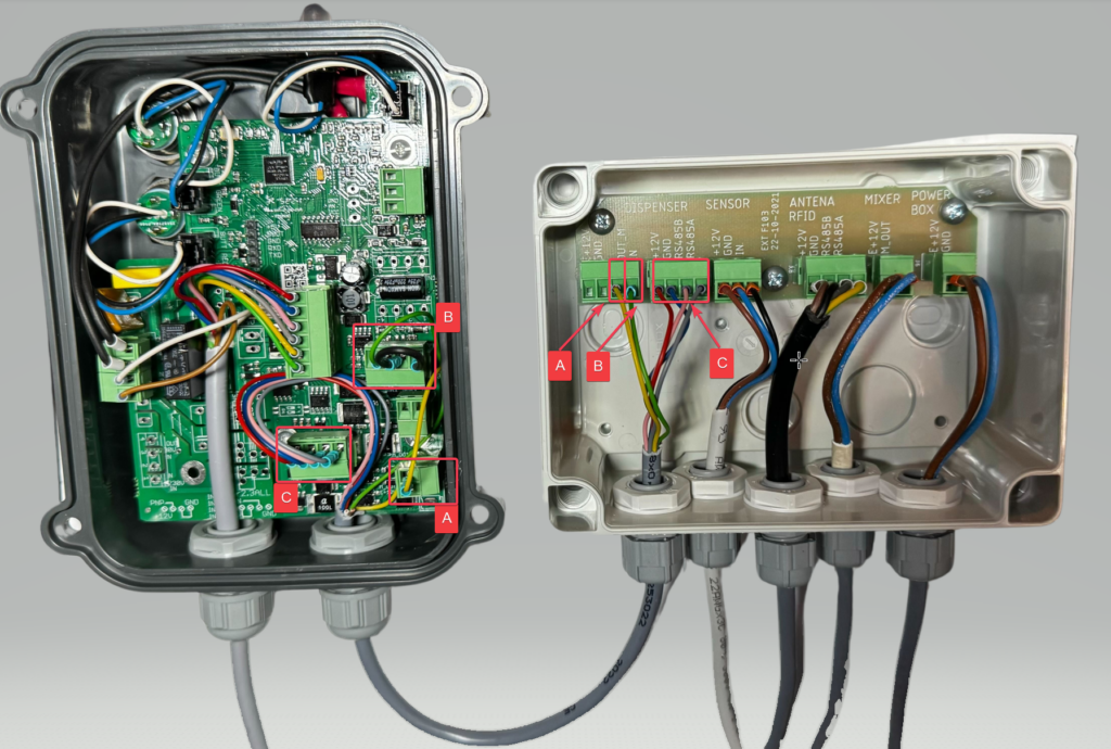
- Remove the 4 mounting screws, open the Nutri GROUP dispenser housing and connect the plugs according to the diagram. Connections are made in pairs: A to A, B to B, C to C
Nutri GROUP – configuration in the application
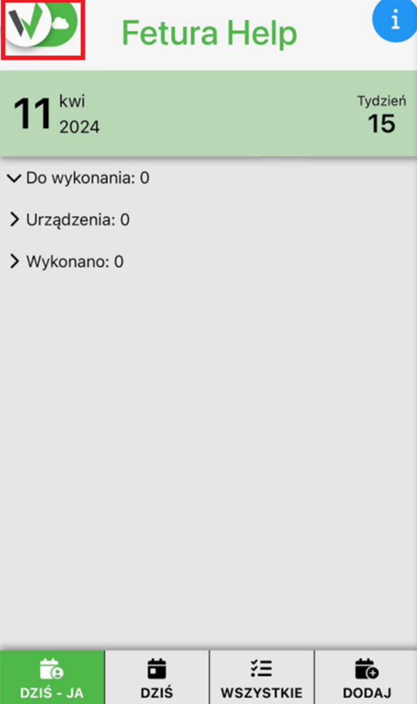
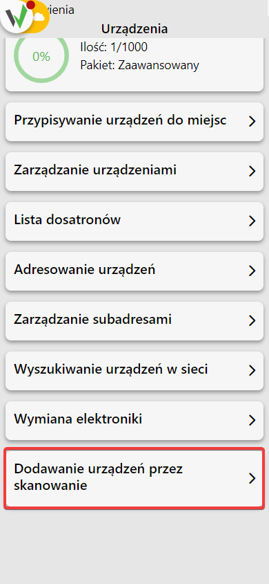
- After logging in, click the highlighted button.
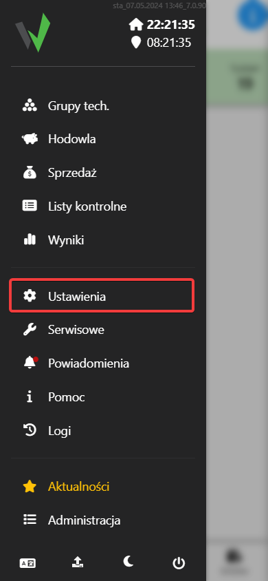
- Scroll down the displayed panel to the very bottom, so that the “Settings” button is visible.
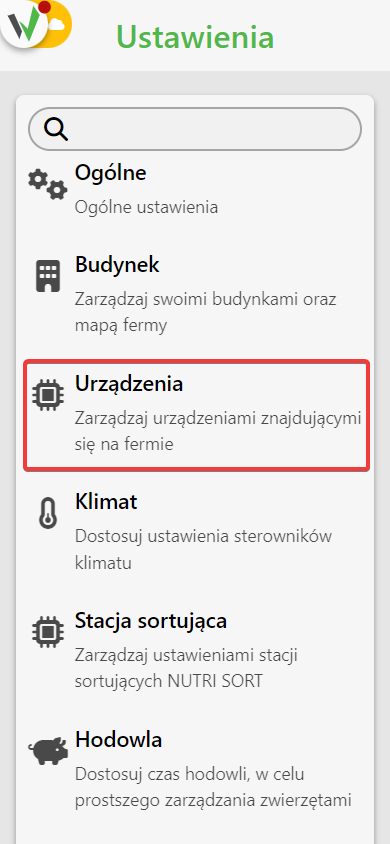
- Go to the “Devices” tab, then in the newly opened window scroll to the very bottom and go to the “Add devices by scanning” tab.
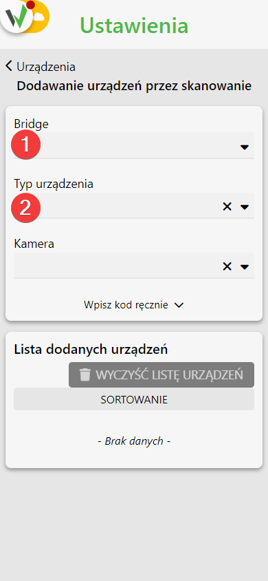
- Select which Bridge you want to add a Nutri GROUP dispenser to [1] and choose to add dispensers from the list [2], then select the Nutri GROUP dispenser type.
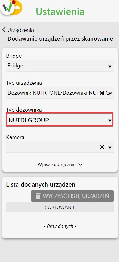
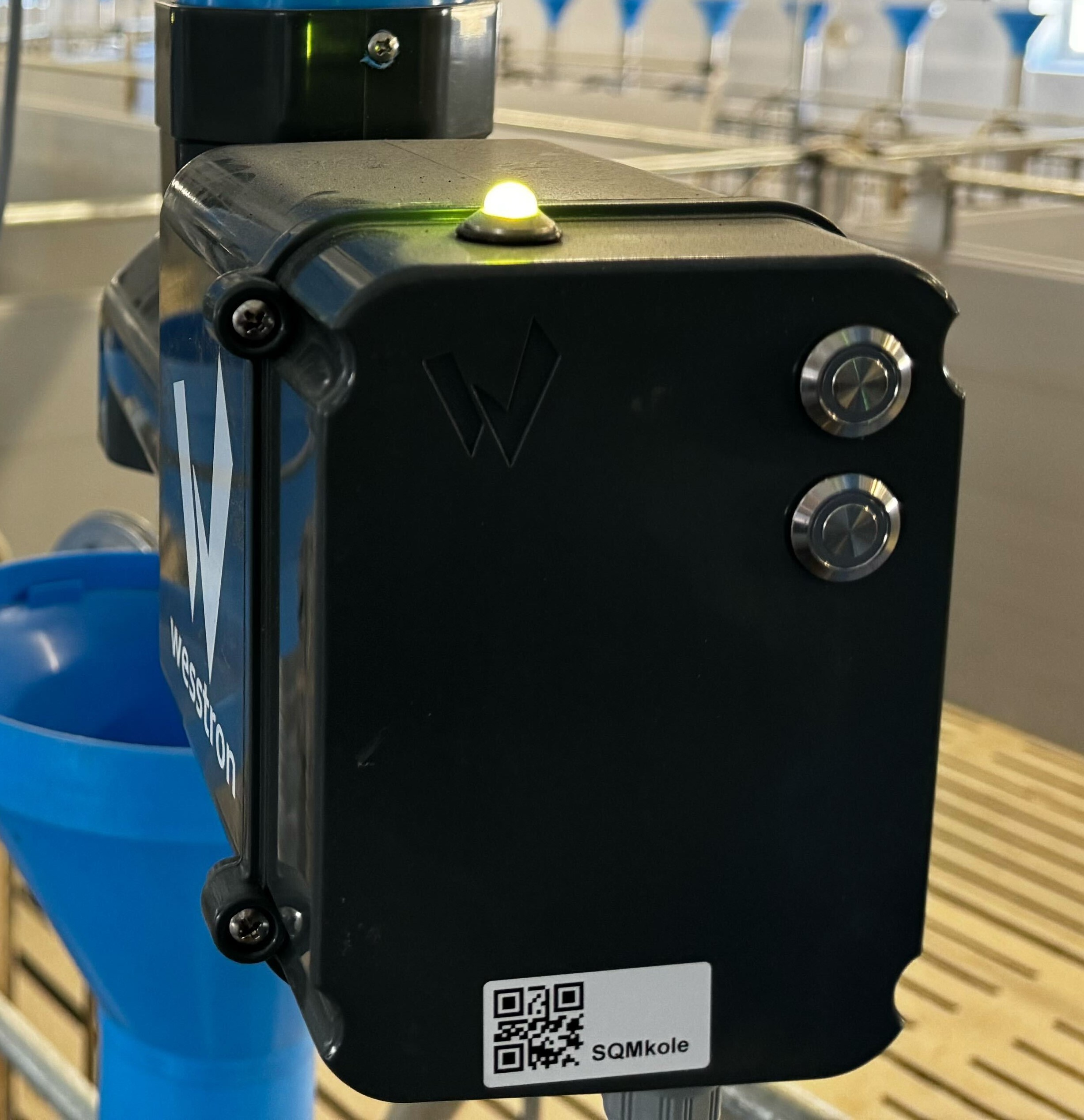
- Scan the QR code on the device case.
Configure the channel, address and subaddress for the dispenser.
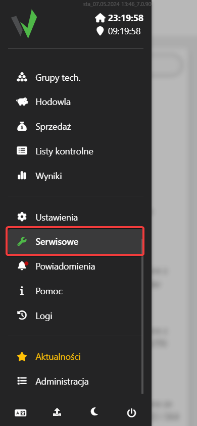
- After logging in, click the highlighted button.

- Then go to the “Service” tab.
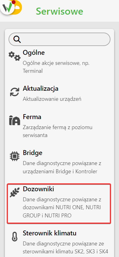
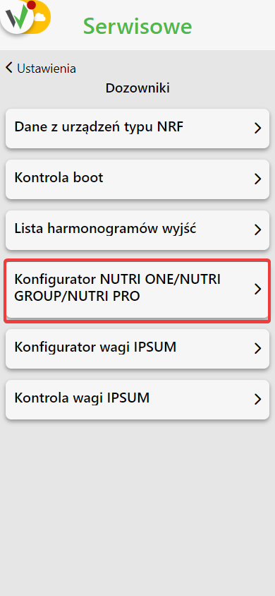
- From the available tabs, select “Dispensers” and then go to the “NUTRI ONE / NUTRI GROUP / NUTI PRO Configurator” tab.
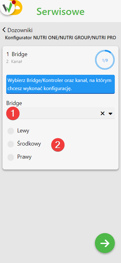
- In the first step, select to which Bridge [1] and on which channel [2] you are adding the Nutri ONE dispenser
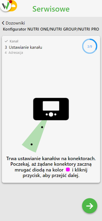
- In the next step, configure the channel. Follow the instructions on the screen.
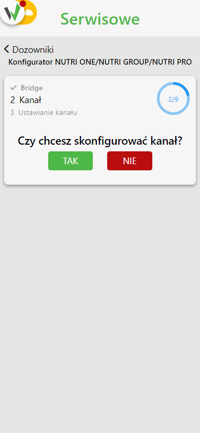
- Disable all connectors that have a different channel and / or has already been previously configured.
- Proceed further to start configuring the channels.
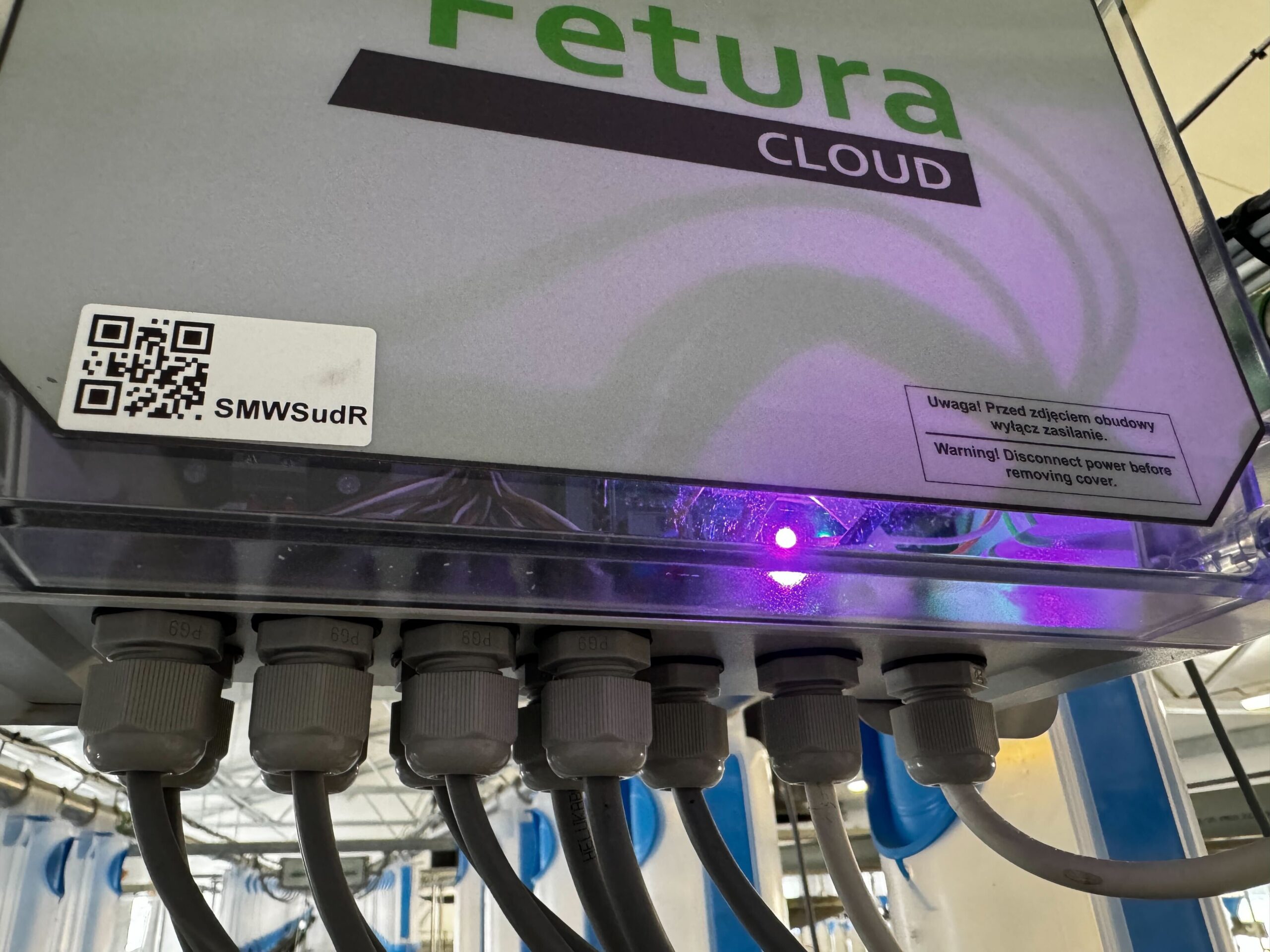
- Wait until the desired connectors start blinking with a pink LED and click the button to proceed.
- In the next step, perform device addressing. Select the starting address from the available address pool [1], specify the number of devices to be addressed [2] and select the addressing mode [3].
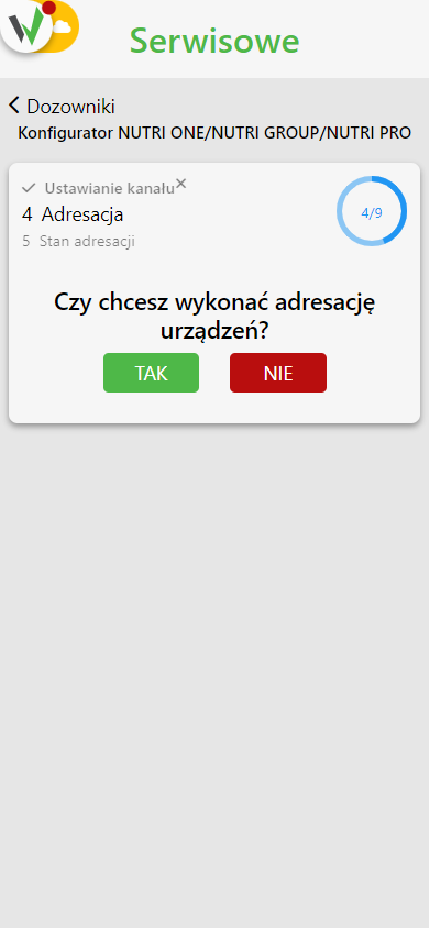
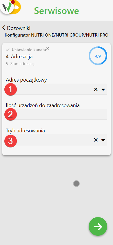
- Follow the instructions on the screen.
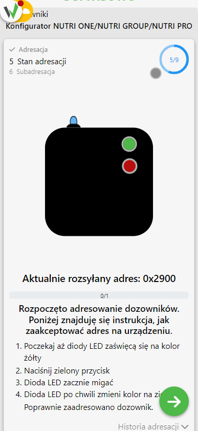
- Wait until the LEDs on the Nutri GROUP dispensers turn yellow.
- Press the top green button on the Nutri GROUP dispenser
- The LED on the dispenser will start flashing.
- The LED on the Nutri GROUP dispenser will turn green after a while. This is a confirmation of correctly performed addressing.
- If you are addressing more than one dispenser wait until the LEDs on the unaddressed Nutri GROUP dispensers turn blue and repeat steps 10 through 12.
- Repeat the steps until you have addressed all devices.
- In the next configuration step, perform subaddressing. Follow the steps on the screen.
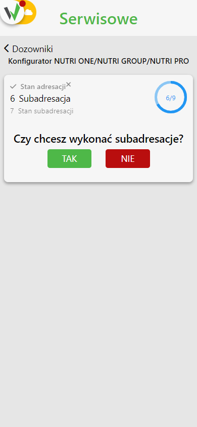

- Check that all Connectors flash the orange LED.
- Press, hold and do not release the top green button on the Nutri GROUP dispenser
- Press, hold and do not let go of the lower red button on the Nutri GROUP dispenser.
- Wait until both buttons blink.
- Release the red button.
- Release the green button. The LED on the dispenser will turn orange.
- Starting from station 1, press the top button on the dispenser. The LED will turn blue.
- Repeat the previous point on subsequent dispensers, in the order in which the positions will be numbered.
- Repeat steps 17 – 23 on the next Connectors.
- Once the last dispenser has been addressed, press the button to move on and complete the subaddressing process.
- Confirm subaddressing
