1. Home
  2. Nutri GROUP- wiring and commissioning

Nutri GROUP- wiring and commissioning

  1. Description of Nutri GROUP dispenser configuration in the application
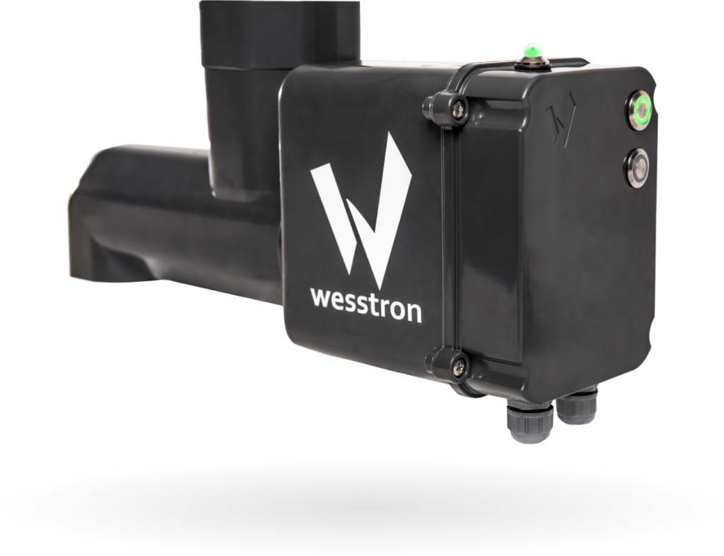
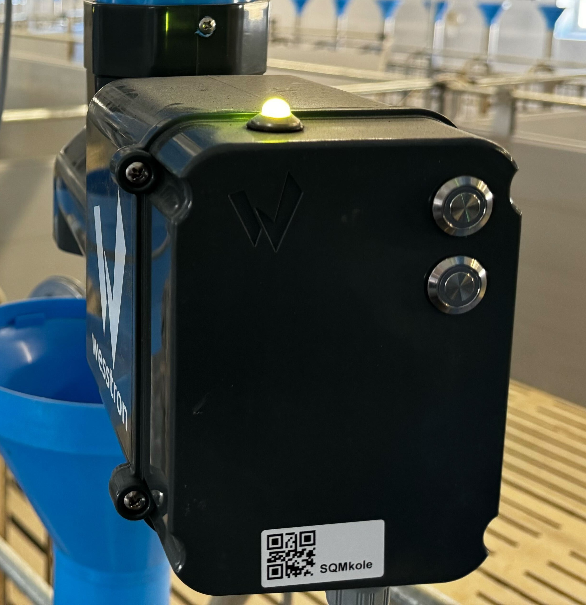
Product photo of the Fetura/Wesstron Nutri GROUP electronic dispenser control unit, showing its black housing, status LED and two push buttons.
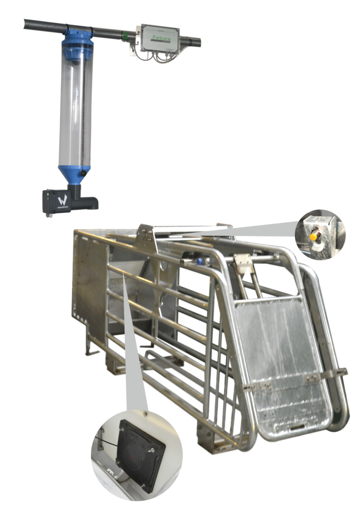
Fig. 1 Nutri GROUP dispenser – high pregnancy sector
Nutri GROUP dispenser mounted above a self-locking cage, with close-up callouts showing the RFID antenna and cage latch sensor mounting locations on the cage frame.
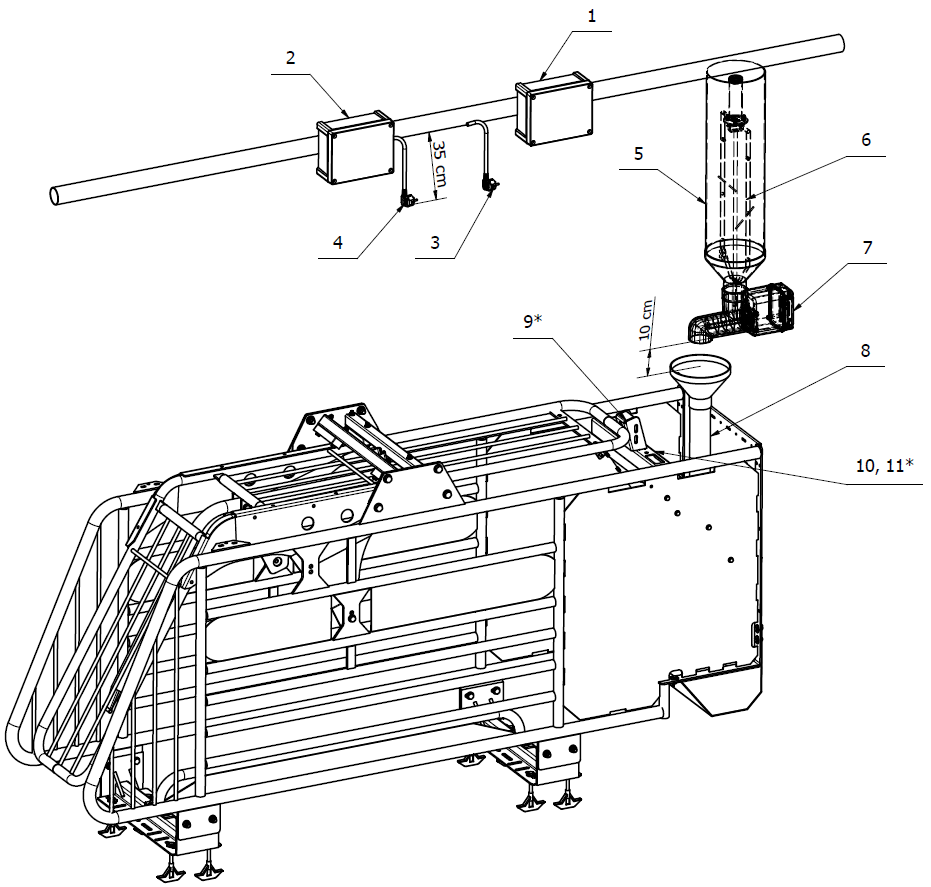
Fig. 2 Nutri GROUP dispenser – installation
Technical line drawing of the Nutri GROUP dispenser installed on a high-pregnancy sector self-locking cage, with leader numbers 1 to 11 keyed to the component table in the article. Numbers 1 and 2 point to the two enclosures mounted on the overhead pipe, 3 and 4 to the hermetic sockets hanging below them, 5 and 6 to the transparent volumetric dispenser tube, 7 to the Nutri GROUP electronic dispenser under the tube, 8 to the trough panel, 9 with an asterisk to the cage latching sensor, and 10, 11 with an asterisk to the trough panel area. The drawing also carries two mounting dimensions given nowhere else in the article: 35 cm from the overhead pipe down to the hermetic socket, and 10 cm from the dispenser outlet down to the top of the drain funnel.
Fig. 3 Nutri GROUP dispenser – list of components
NumberDescription
1Connector or Connector Extension (type of device depends on the technological design)
2Power Box (optional)
3YDY 3 x 1.5mm2 cable terminated with a hermetic socket
4YDY 3 x 1.5mm2 cable terminated with a hermetic socket (optional)
5Volumetric dispenser
6Mixer (optional
7Nutri GROUP electronic dispenser
8Drain pipe
9Self-locking cage latching sensor (optional)
10RFID antenna
11Nutri GROUP adapter (optional)

Choose which device you will be connecting the Nutri GROUP dispenser to
Connector
Connector Extension

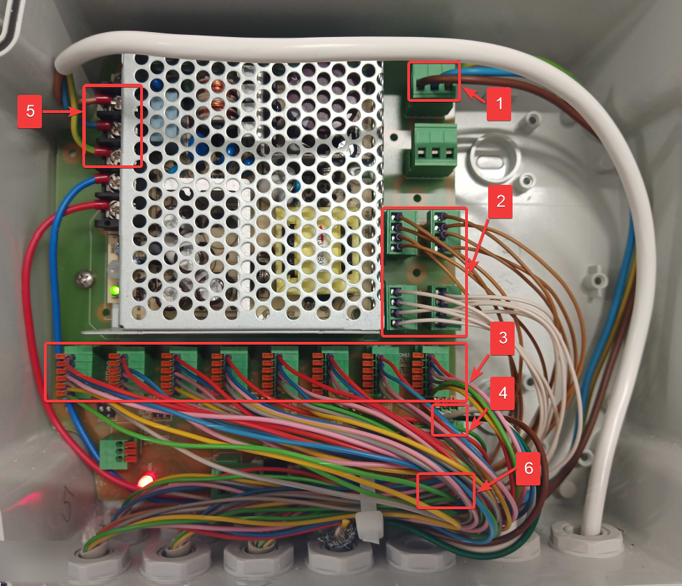
Nutri GROUP – wiring diagram for the Connector
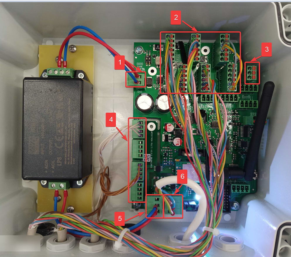
Inside the Connector enclosure with numbered red boxes 1-6 marking the main power input, dispenser inputs, CAN output to the Extension, 230VAC dispenser supply, DC power supply output, and mains input terminals, matching the wiring diagram.
Fig. 4 Connector – wiring diagram of Nutri GROUP dispenser
NumberDescription
1Main power supply 12 VDC (from the top: +12 VDC, GND)
2Inputs for Nutri GROUP dispensers(max 8 pcs).
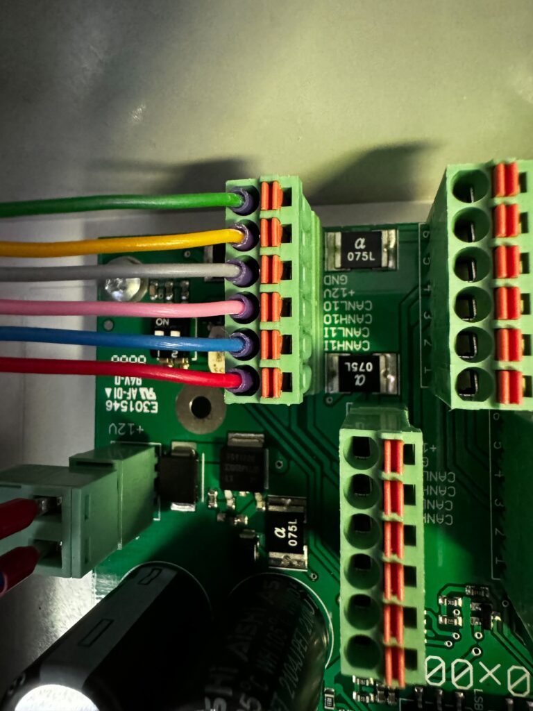
(from top: +12VDC, GND, CANLxO, CANHxO, CANLxI, CANHxI)
See Figure 5
3CAN communication output to Connector – Extension (from top: GND, CANL, CANH)
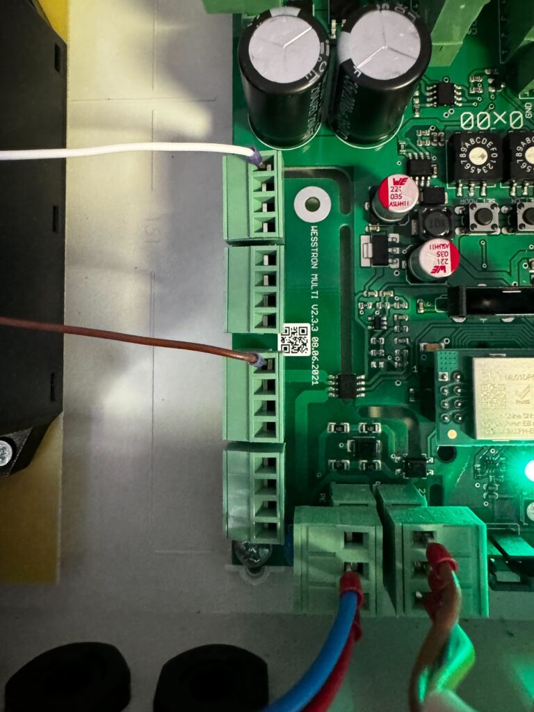
4230 VAC power supply for Nutri GROUP dispensers (from the top: N, L)
See Figure 6
5Output 230 VAC to built-in DC power supply (from top: PE, N, L)
6Input 230 VAC – main power supply of the Connector (from the top: L, N, PE)
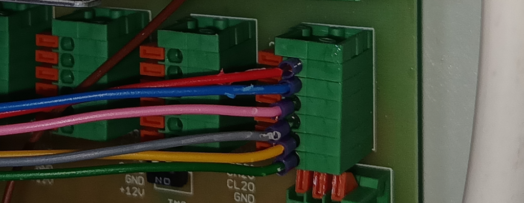
Close-up of the Connector's power and CAN communication terminal block with the +12VDC, GND, CANL and CANH wires connected.
Fig. 5 Nutri GROUP – power and CAN communication connection
Close-up of the Connector's 230VAC power supply terminal block with the white and brown mains wires connected.
Fig. 6 Nutri GROUP – 230 VAC power supply connection

Nutri GROUP – wiring diagram for Extension Connector
Inside the Connector Extension enclosure with numbered red boxes 1-5 marking the 230VAC input, Nutri ONE power supply, dispenser inputs, CAN communication input, and DC power supply input terminals.
Fig. 7 Connector Extension – Nutri GROUP dispenser wiring diagram
NumberDescription
1230 VAC input – serial connection from Connector (from left: L, N, PE)
2230 VAC power supply for Nutri ONE dispensers (from the top: N, L)
See Figure 9
3Inputs for Nutri GROUP dispensers (max 8 pcs).
(from bottom: +12VDC, GND, CANLxO, CANHxO, CANLxI, CANHxI)
See Figure 8
4CAN communication input on Connector – Extension (from the left: GND, CANL, CANH)
5230 VAC input for built-in DC power supply (from the top: L, N, PE)
6Main power supply 12 VDC (from the top: GND, +12 VDC)
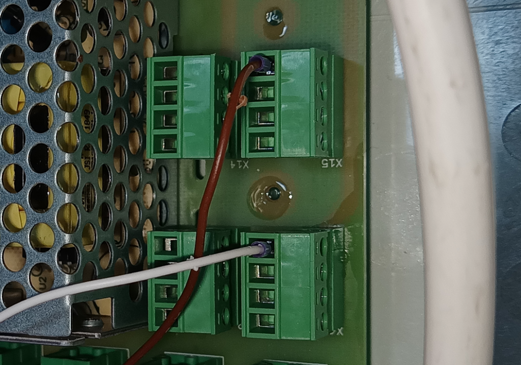
Close-up of the Connector Extension's X14/X15 terminal blocks with the white and brown wires connected for the built-in DC power supply.
Fig. 8 Nutri GROUP – power and CAN communication connection
Close-up of a terminal block on the Extension board with red and white wires connected, supplying 12VDC power to the built-in DC power supply.
Fig. 9 Nutri GROUP – 230 VAC power supply connection

Nutri GROUP – connecting RFID antenna, mixer and cage latch sensor

Choose which device you will connect the RFID antenna to:
a) Nutri GROUP dispenser(basic version)
(b) Nutri GROUP adapter(extended version with accessories)

Important!
The cable from the RFID antenna should be routed along the structure of the self-locking cage, so that animals do not have access to it.

Basic version

  1. Mount the wire from the RFID antenna to the self-locking cage structure
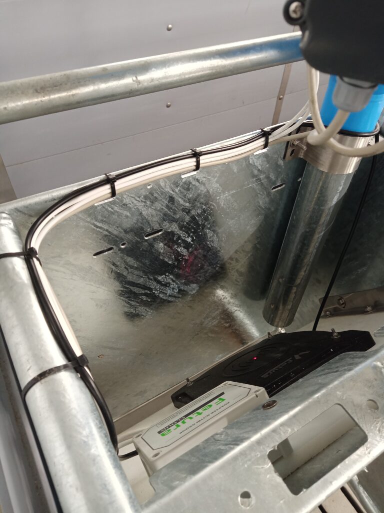
RFID antenna cable routed and zip-tied along the self-locking cage frame toward the Nutri GROUP dispenser housing.
  1. Remove the 4 mounting screws and open the Nutri GROUP dispenser housing
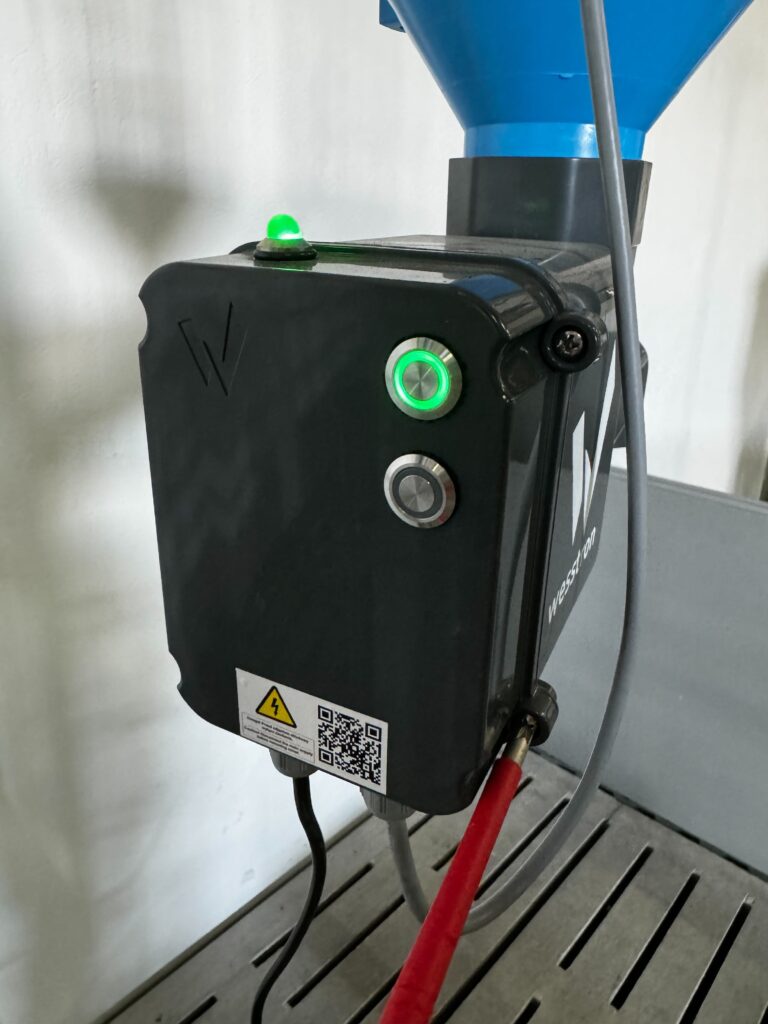
Nutri GROUP dispenser mounted below the feed hopper with its green power LED lit and cables connected at the bottom of the housing.
  1. Insert the cable from the antenna through the choke in the Nutri GROUP dispenser housing
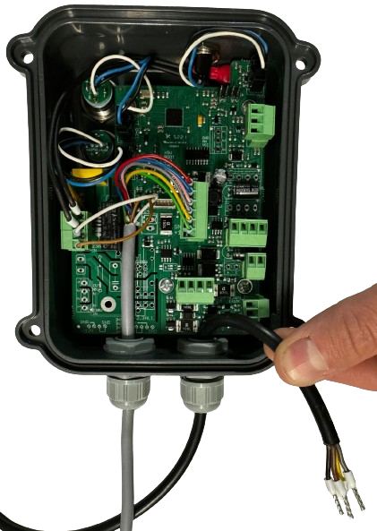
Open Nutri GROUP dispenser housing with the 4 mounting screws removed, showing a hand feeding the RFID antenna cable through the cable gland.
  1. Connect the wire from the RFID antenna to the plug
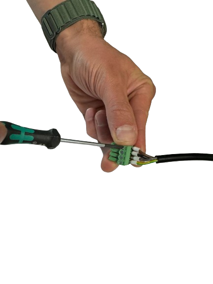
Hand using a screwdriver to connect the bare RFID antenna wire into a small green plug connector.
  1. Connect the plug to the socket from the RFID antenna
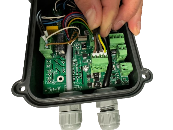
Hand plugging the RFID antenna connector into its socket on the green PCB inside the open Nutri GROUP dispenser housing.
  1. Close the Nutri GROUP dispenser housing and tighten the 4 mounting screws
Nutri GROUP dispenser mounted below the feed hopper with its green power LED lit and cables connected at the bottom of the housing.

Enhanced version – Nutri GROUP adapter (RFID antenna)

  1. Mount the wire from the RFID antenna on the self-locking cage structure and feed it through the choke into the Nutri GROUP adapter
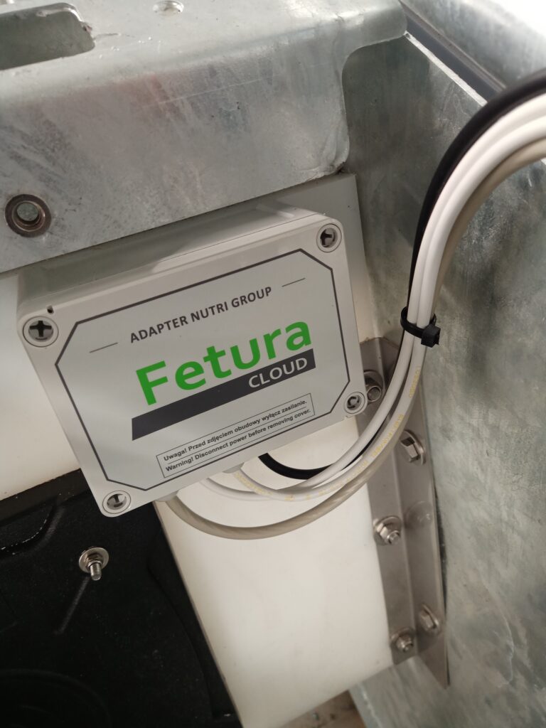
RFID antenna cable routed and zip-tied along the self-locking cage frame toward the Nutri GROUP dispenser housing.
Nutri GROUP adapter housing labeled "Adapter Nutri Group" mounted on the cage frame, with cables entering through a cable gland from the self-locking cage structure.
  1. Unscrew the 4 mounting screws, open the Nutri GROUP adapter housing and connect the plug to the socket from the RFID antenna
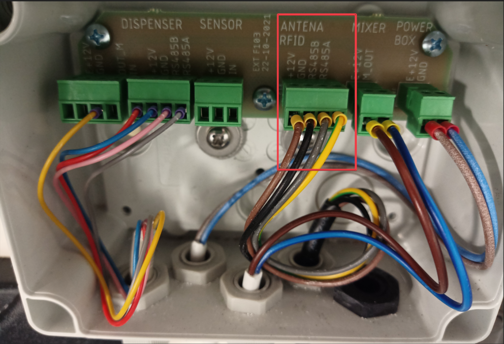
Inside the Nutri GROUP adapter, board marked EXT F103 22-10-2021, with a red box highlighting the ANTENA RFID terminal block and its connected wires. The board carries six screw terminal blocks; the silkscreen from left to right reads: DISPENSER above two blocks, the first with pins +12V, GND, OUT_M, IN and the second with pins +12V, GND, RS485B, RS485A; SENSOR with pins +12V, GND, IN; ANTENA RFID with pins +12V, GND, RS485B, RS485A; MIXER with pins E+12V, M_OUT; POWER BOX with pins E+12V, GND. Cables enter the enclosure through five cable glands along the bottom edge.

Enhanced version – Nutri GROUP adapter (stirrer)

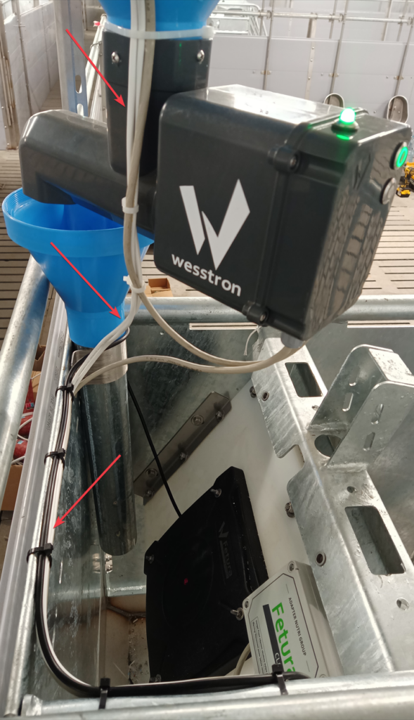
  1. Run the cable from the mixer along the volumetric dispenser, then mount it on the self-blocking cage structure and feed it through the choke into the Nutri GROUP adapter
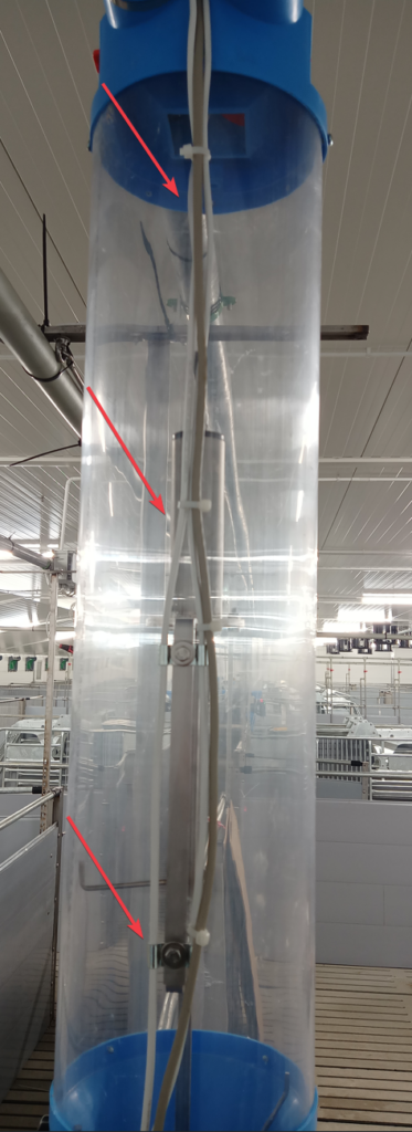
Volumetric dispenser tube with the RFID antenna cable routed and zip-tied along its length, red arrows marking the tie-down points.
Nutri GROUP dispenser and adapter with red arrows showing the RFID antenna and mixer cables routed along the dispenser tube down into the adapter housing.
Nutri GROUP adapter housing labeled "Adapter Nutri Group" mounted on the cage frame, with cables entering through a cable gland from the self-locking cage structure.
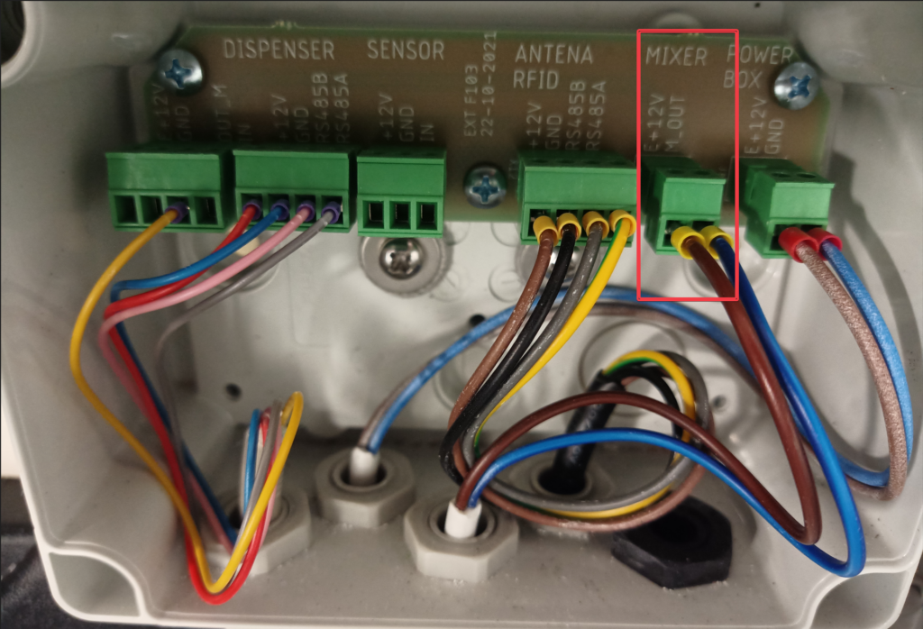
  1. Remove the 4 mounting screws, open the Nutri GROUP adapter housing and connect the plug to the socket from the mixer
Inside the Nutri GROUP adapter, board marked EXT F103 22-10-2021, with a red box highlighting the MIXER terminal block and its connected wires. The silkscreen on the board labels six terminal blocks, from left to right: DISPENSER above two blocks, the first with pins +12V, GND, OUT_M, IN and the second with pins +12V, GND, RS485B, RS485A; SENSOR with pins +12V, GND, IN; ANTENA RFID with pins +12V, GND, RS485B, RS485A; MIXER with pins E+12V, M_OUT; POWER BOX with pins E+12V, GND.

Enhanced version – Nutri GROUP adapter (latch sensor)

  1. Mount the cable from the latching sensor on the self-locking cage structure and feed it through the choke into the Nutri GROUP adapter
Nutri GROUP adapter housing labeled "Adapter Nutri Group" mounted on the cage frame, with cables entering through a cable gland from the self-locking cage structure.
  1. Remove the 4 mounting screws, open the Nutri GROUP adapter housing and connect the plug to the socket from the snap sensor
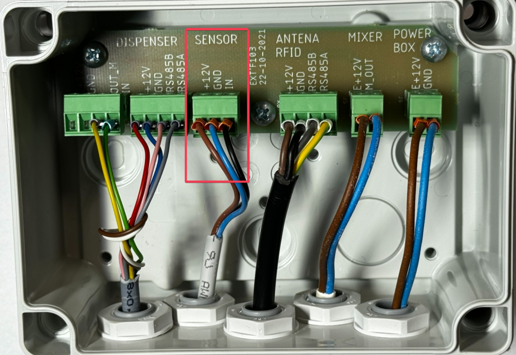
Inside the Nutri GROUP adapter, board marked EXT F103 22-10-2021, with a red box highlighting the SENSOR terminal block used for the cage latch sensor and its brown, blue and black wires. The silkscreen on the board labels six terminal blocks, from left to right: DISPENSER above two blocks, the first with pins +12V, GND, OUT_M, IN and the second with pins +12V, GND, RS485B, RS485A; SENSOR with pins +12V, GND, IN; ANTENA RFID with pins +12V, GND, RS485B, RS485A; MIXER with pins E+12V, M_OUT; POWER BOX with pins E+12V, GND.

Extended version – connecting the adapter to the Nutri GROUP dispenser

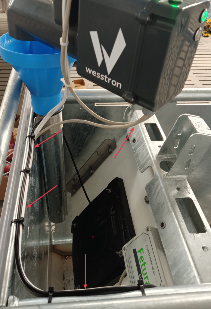
  1. Mount the cable from the Nutri GROUP adapter on the self-locking cage structure and feed it through the choke into the Nutri GROUP dispenser
Nutri GROUP adapter housing labeled "Adapter Nutri Group" mounted on the cage frame, with cables entering through a cable gland from the self-locking cage structure.
Nutri GROUP dispenser with red arrows showing the mixer cable routed along the dispenser tube and cage frame down to the adapter housing.
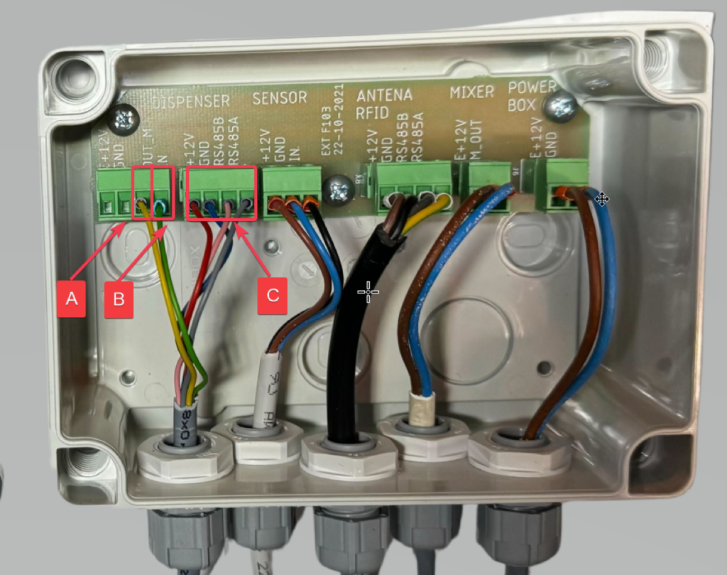
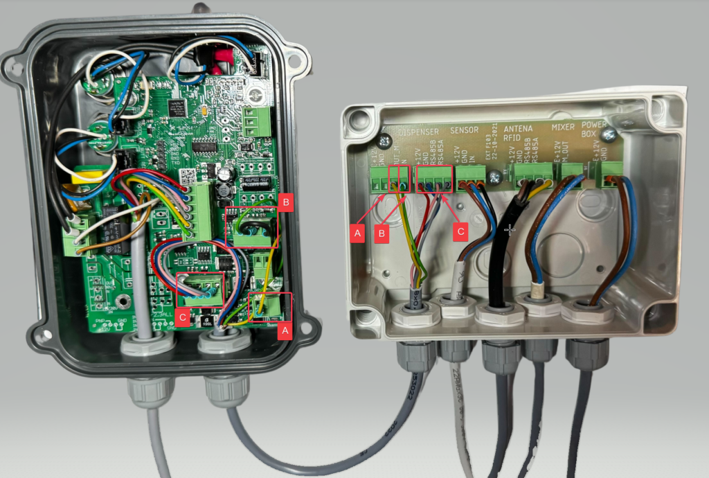
  1. Remove the 4 mounting screws, open the Nutri GROUP dispenser housing and connect the plugs according to the diagram. Connections are made in pairs: A to A, B to B, C to C
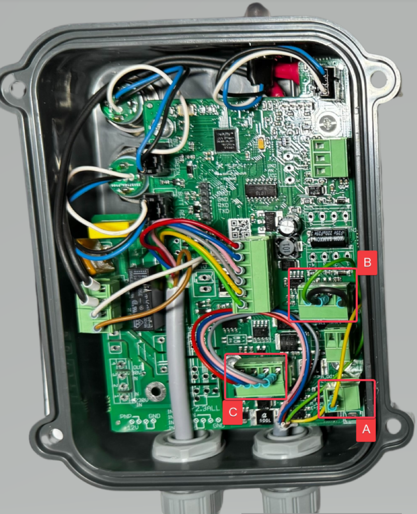
Inside the Nutri GROUP dispenser housing, with three red boxes labeled A, B and C marking the plug pairs used to connect the Nutri GROUP adapter cable.
Inside the Nutri GROUP dispenser housing, terminal board with red boxes labeled A, B and C marking the Dispenser and Sensor connectors that pair with the adapter's plugs.
Two open device housings side by side, the Nutri GROUP dispenser board and the adapter board, with matching red boxes A, B and C showing which plugs connect to each other.

Nutri GROUP – configuration in the application

  1. After logging in, click the highlighted button.
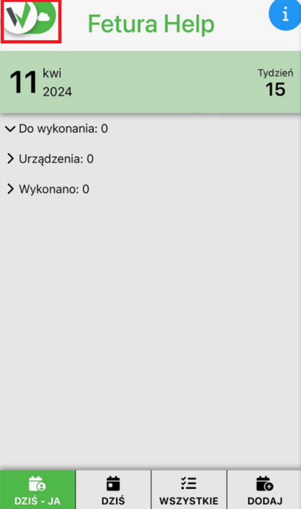
Fetura Help mobile app home screen with a red box around the app logo button in the top-left corner, used to open the main menu.
  1. Scroll down the displayed panel to the very bottom, so that the “Settings” button is visible.
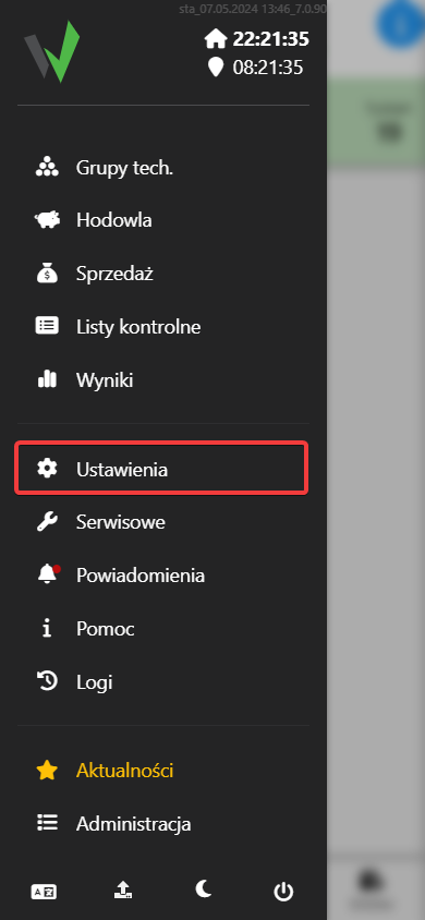
Fetura CLOUD sidebar menu with the Settings (Ustawienia) item highlighted in red, used to open the settings panel.
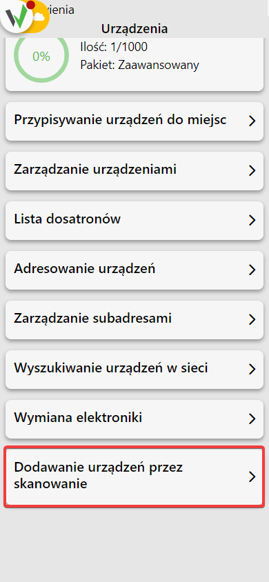
  1. Go to the “Devices” tab, then in the newly opened window scroll to the very bottom and go to the “Add devices by scanning” tab.
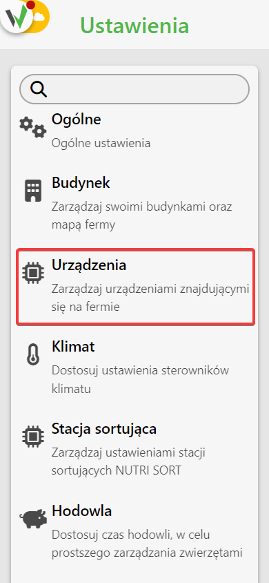
Settings screen list with the Devices (Urządzenia) option highlighted in red, used to open device management.
Devices menu list with the "Add devices by scanning" (Dodawanie urządzeń przez skanowanie) option highlighted in red.
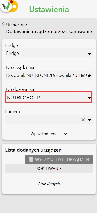
  1. Select which Bridge you want to add a Nutri GROUP dispenser to [1] and choose to add dispensers from the list [2], then select the Nutri GROUP dispenser type.
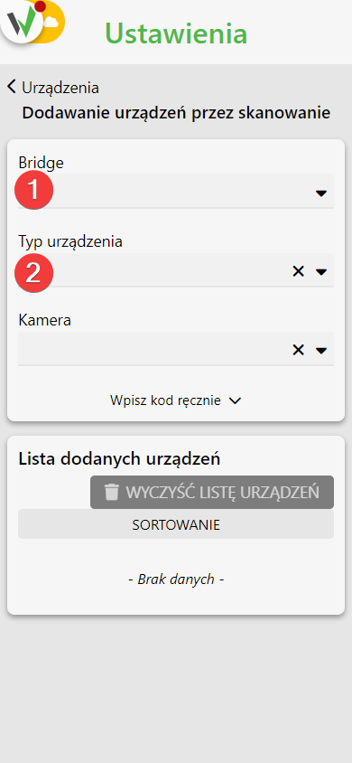
Add devices by scanning form, with red numbered circles 1 and 2 marking the Bridge dropdown and the device type dropdown to fill in.
Device type step of the 'Dodawanie urządzeń przez skanowanie' (add devices by scanning) form, with the 'Typ dozownika' (dispenser type) dropdown set to NUTRI GROUP and highlighted in red. The fields on this screen, from the top, are: Bridge, Typ urządzenia (device type) set to 'Dozownik NUTRI ONE/Dozowniki NUTRI GROUP', Typ dozownika, and Kamera, which selects the camera used for scanning. Below them is an expandable 'Wpisz kod ręcznie' (enter the code manually) section, an alternative to scanning the QR code. The lower card 'Lista dodanych urządzeń' (list of added devices) has the buttons WYCZYŚĆ LISTĘ URZĄDZEŃ and SORTOWANIE and currently reads '- Brak danych -' (no data).
  1. Scan the QR code on the device case.
Close-up of the Nutri GROUP/ONE dispenser housing showing the QR code label used for scanning, with an LED indicator and two push buttons.

Configure the channel, address and subaddress for the dispenser.

  1. After logging in, click the highlighted button.
Fetura Help mobile app home screen with a red box around the app logo button in the top-left corner, used to open the main menu.
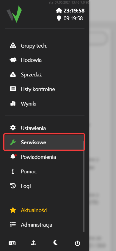
  1. Then go to the “Service” tab.
Fetura CLOUD sidebar menu with the Service (Serwisowe) item highlighted in red.
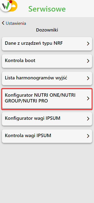
  1. From the available tabs, select “Dispensers” and then go to the “NUTRI ONE / NUTRI GROUP / NUTI PRO Configurator” tab.
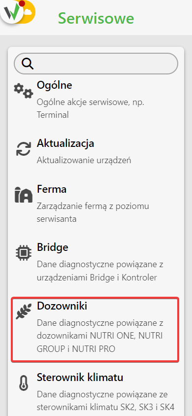
Service menu list with the Dispensers (Dozowniki) option highlighted in red.
Dispensers service menu with the "NUTRI ONE/NUTRI GROUP/NUTRI PRO Configurator" option highlighted in red.
  1. In the first step, select to which Bridge [1] and on which channel [2] you are adding the Nutri ONE dispenser
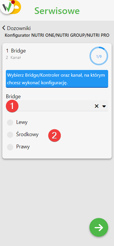
First step of the dispenser configurator, with red numbered circles 1 and 2 marking the Bridge dropdown and the channel selection (Left/Middle/Right).
  1. In the next step, configure the channel. Follow the instructions on the screen.
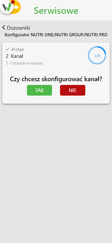
Configurator step for the channel, asking "Do you want to configure the channel?" with green Yes and red No buttons.
  1. Disable all connectors that have a different channel and / or has already been previously configured.
  2. Proceed further to start configuring the channels.
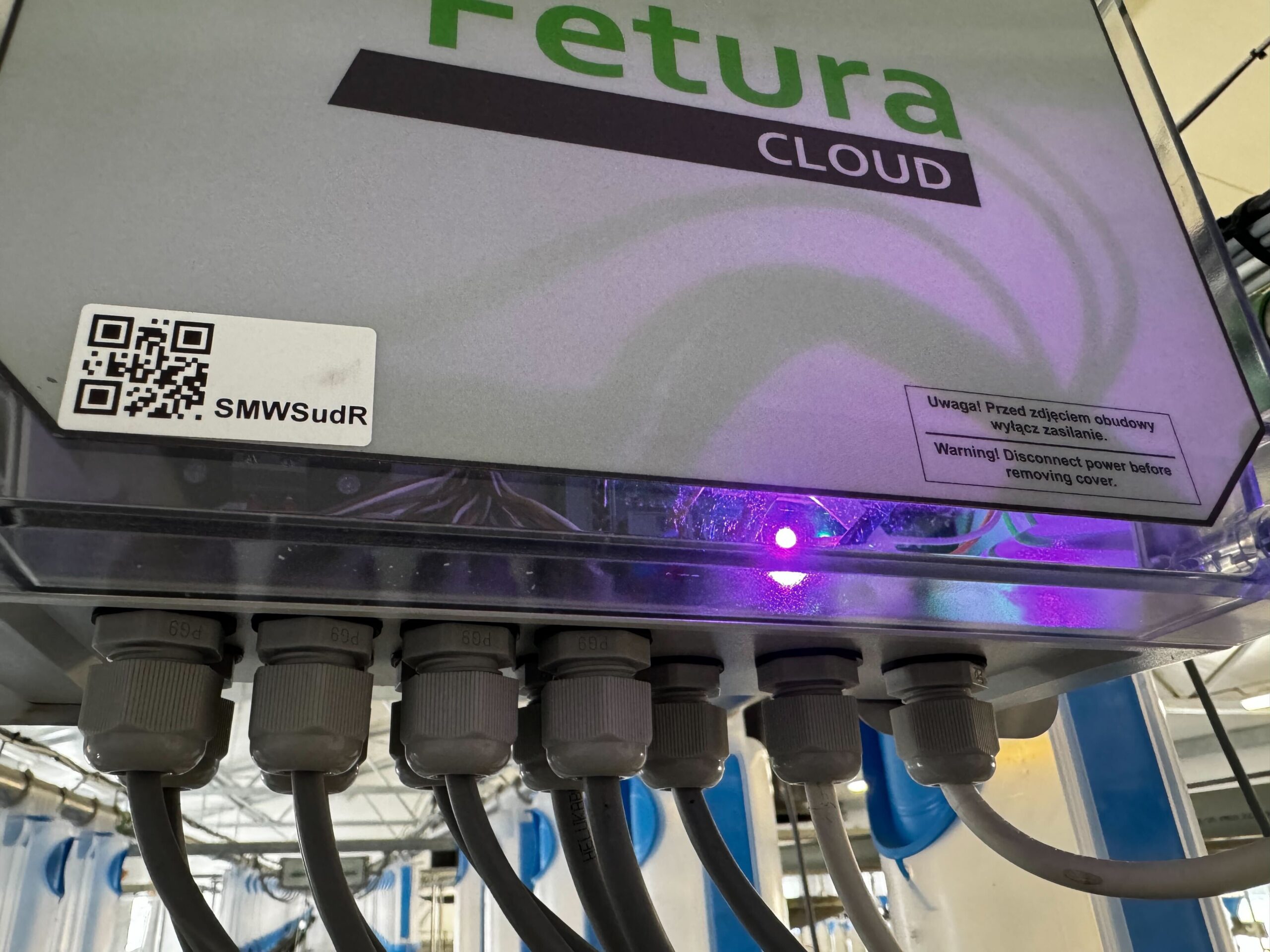
  3. Wait until the desired connectors start blinking with a pink LED and click the button to proceed.
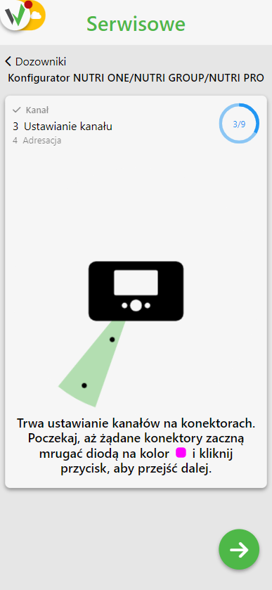
Configurator screen showing an illustration of a Connector device with a signal icon, instructing the user to wait until the desired connectors blink pink and then continue.
Close-up of a Fetura CLOUD Connector enclosure with its QR code label and a pink/purple LED lit inside, matching the "connector blinking pink" step.
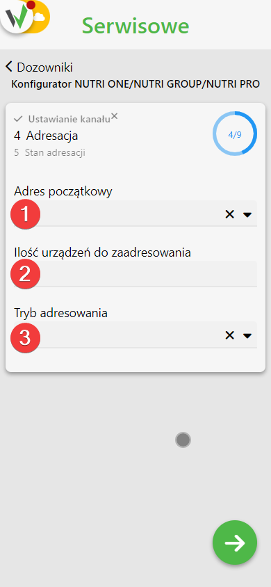
  1. In the next step, perform device addressing. Select the starting address from the available address pool [1], specify the number of devices to be addressed [2] and select the addressing mode [3].
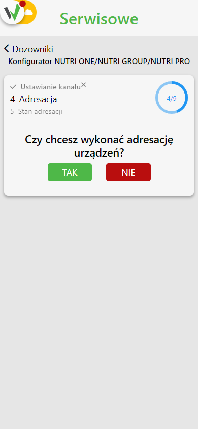
Configurator step for addressing, asking "Do you want to perform device addressing?" with green Yes and red No buttons.
Addressing configuration form with red numbered circles 1, 2 and 3 marking the starting address, number of devices to address, and addressing mode fields.
  1. Follow the instructions on the screen.
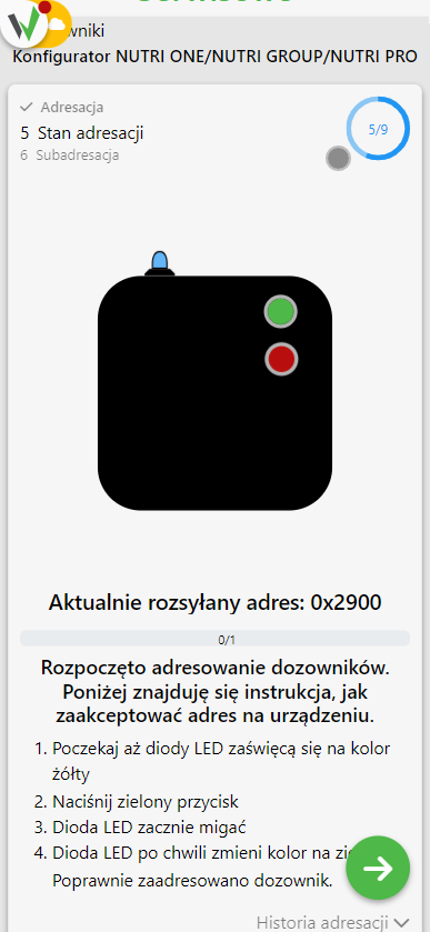
Configurator addressing status screen with a dispenser illustration and the currently broadcast address, listing the steps to accept the address on the device (wait for yellow LED, press the green button, wait for it to turn green).
  1. Wait until the LEDs on the Nutri GROUP dispensers turn yellow.
  2. Press the top green button on the Nutri GROUP dispenser
  3. The LED on the dispenser will start flashing.
  4. The LED on the Nutri GROUP dispenser will turn green after a while. This is a confirmation of correctly performed addressing.
  5. If you are addressing more than one dispenser wait until the LEDs on the unaddressed Nutri GROUP dispensers turn blue and repeat steps 10 through 12.
  6. Repeat the steps until you have addressed all devices.
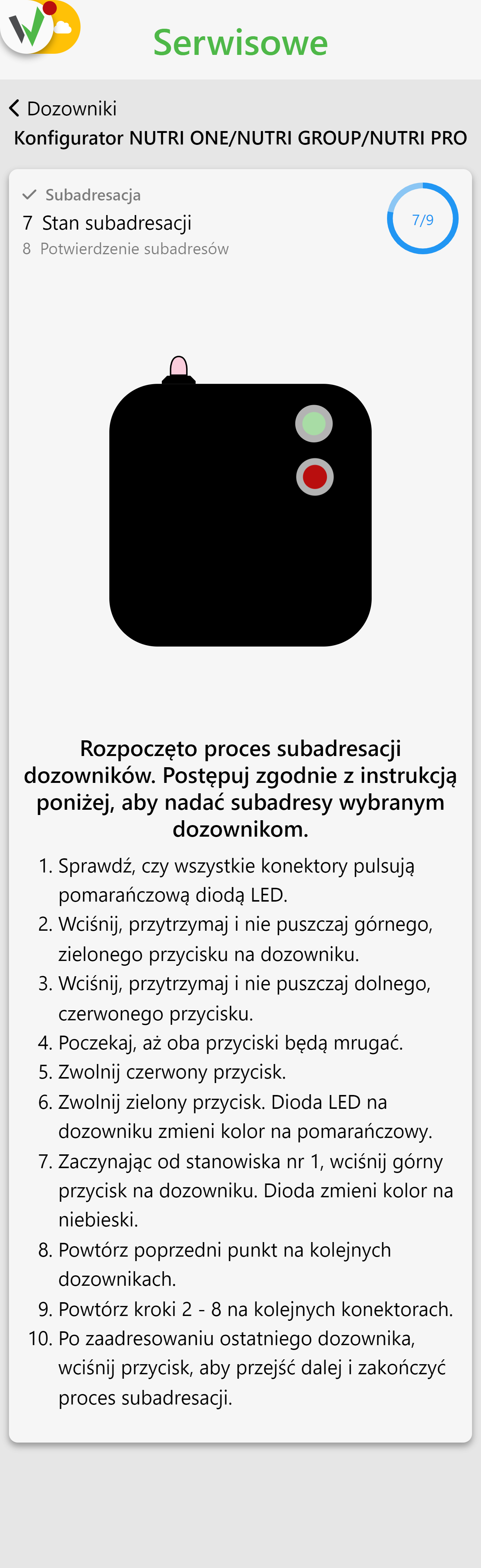
  7. In the next configuration step, perform subaddressing. Follow the steps on the screen.
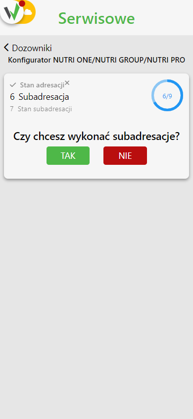
Configurator step for sub-addressing, asking "Do you want to perform sub-addressing?" with green Yes and red No buttons.
Configurator sub-addressing status screen with a dispenser illustration and a 10-step instruction list for pressing and holding the green and red buttons to assign sub-addresses.
  1. Check that all Connectors flash the orange LED.
  2. Press, hold and do not release the top green button on the Nutri GROUP dispenser
  3. Press, hold and do not let go of the lower red button on the Nutri GROUP dispenser.
  4. Wait until both buttons blink.
  5. Release the red button.
  6. Release the green button. The LED on the dispenser will turn orange.
  7. Starting from station 1, press the top button on the dispenser. The LED will turn blue.
  8. Repeat the previous point on subsequent dispensers, in the order in which the positions will be numbered.
  9. Repeat steps 17 – 23 on the next Connectors.
  10. Once the last dispenser has been addressed, press the button to move on and complete the subaddressing process.
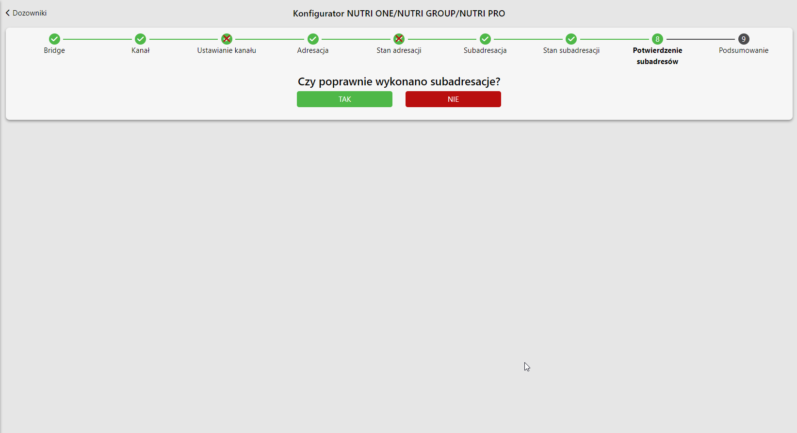
  11. Confirm subaddressing
Desktop view of the NUTRI ONE/NUTRI GROUP/NUTRI PRO configurator at the sub-address confirmation step, asking 'Czy poprawnie wykonano subadresacje?' (was sub-addressing performed correctly) with a green TAK button and a red NIE button. The progress bar at the top names all nine steps of the configurator in order: 1 Bridge, 2 Kanal (channel), 3 Ustawianie kanalu (setting the channel), 4 Adresacja (addressing), 5 Stan adresacji (addressing status), 6 Subadresacja (sub-addressing), 7 Stan subadresacji (sub-addressing status), 8 Potwierdzenie subadresow (sub-address confirmation), 9 Podsumowanie (summary). Step 8 is the current one and step 9 is still inactive.

Nutri GROUP – assigning dispensers to group pens

Assigning dispensers to group pens is described in the article: How to assign a dispenser to a group crate?

Nutri GROUP – basic configuration of dispensers

Configuring Nutri GROUP dispensers is described in the article: How to configure a Nutri GROUP dispenser?

Nutri GROUP – feed calibration

Feed calibration of Nutri GROUP dispensers is described in the article: How to calibrate feeding efficiency?

Updated on 2026-07-28
Was this article helpful?
Need Support?
Can't find the answer you're looking for?
Contact Support

Leave a Comment