1. Wiring
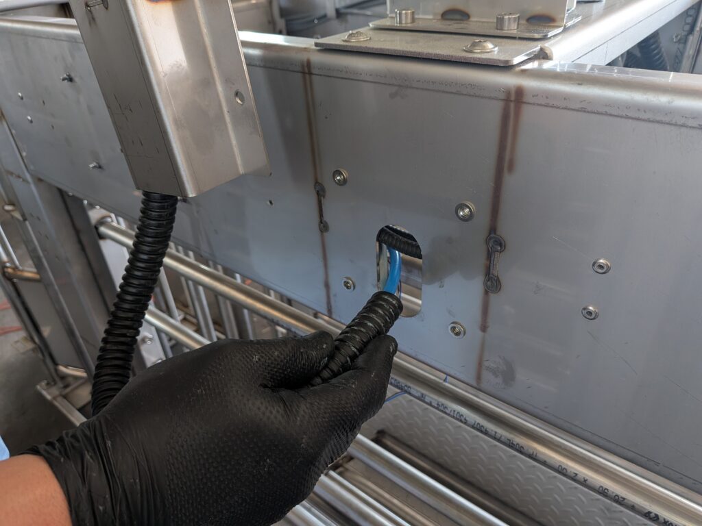
The first step is to route the cables, plugs, air hose, and conduit through the mounting hole on the left side of the cage.
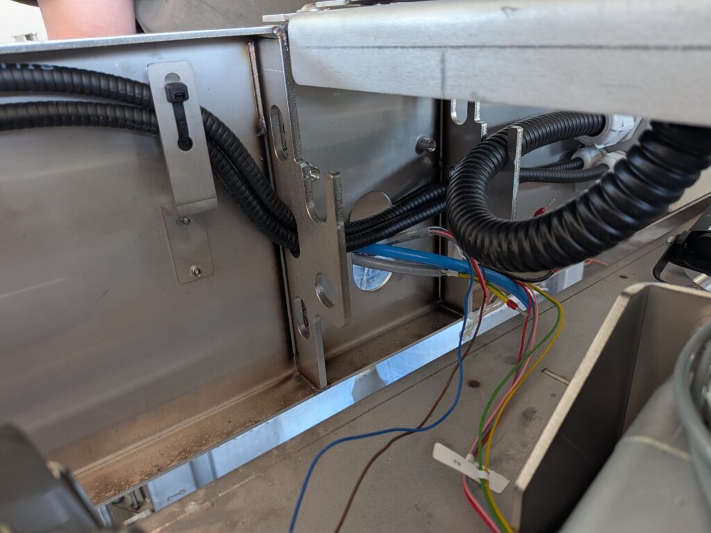
2. Post Installation
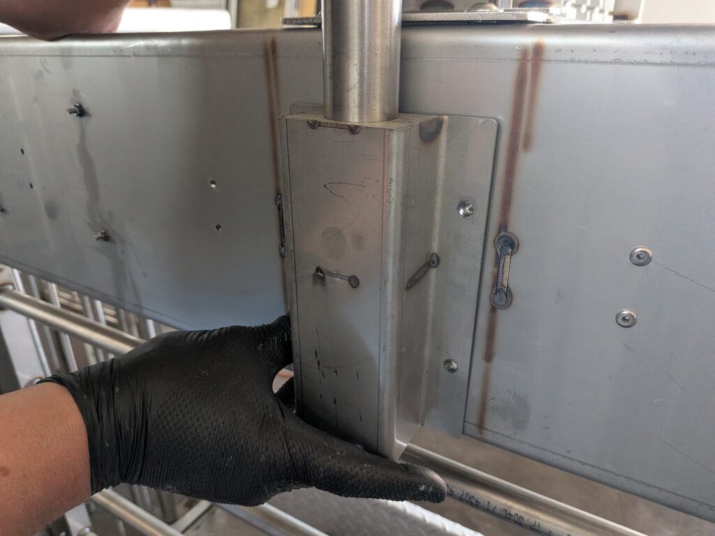
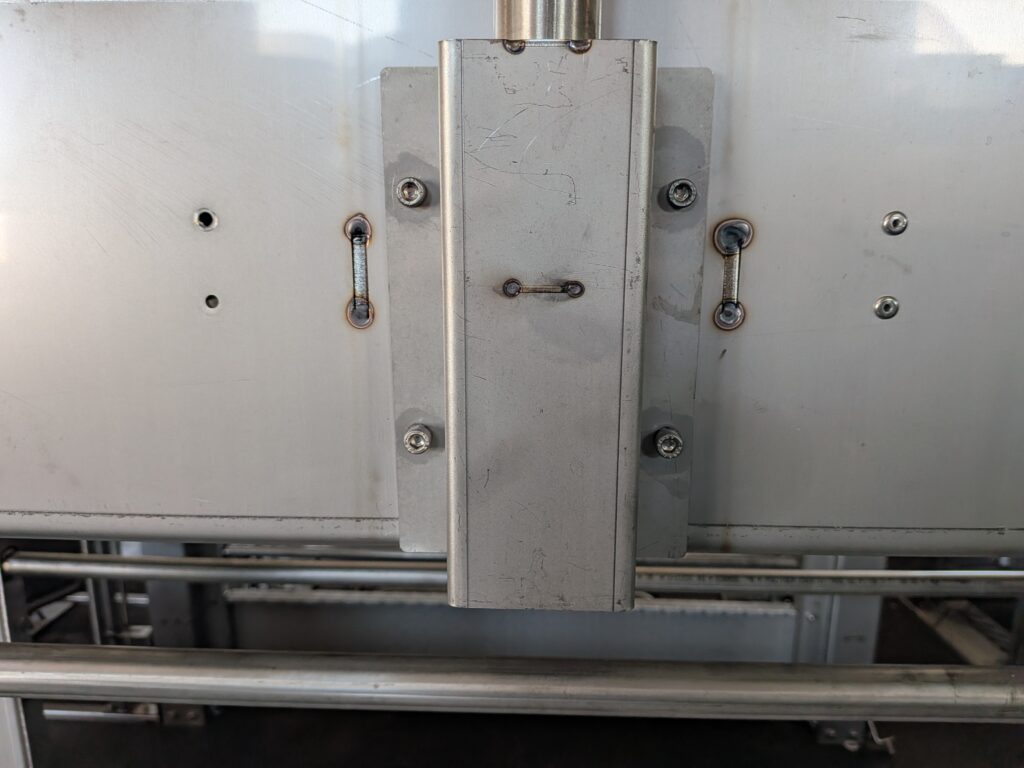
After routing the wires, secure the post with 4 M6 × 16 mm Allen screws. The screws are included in the mounting kit.
3. Running the wires to the controller
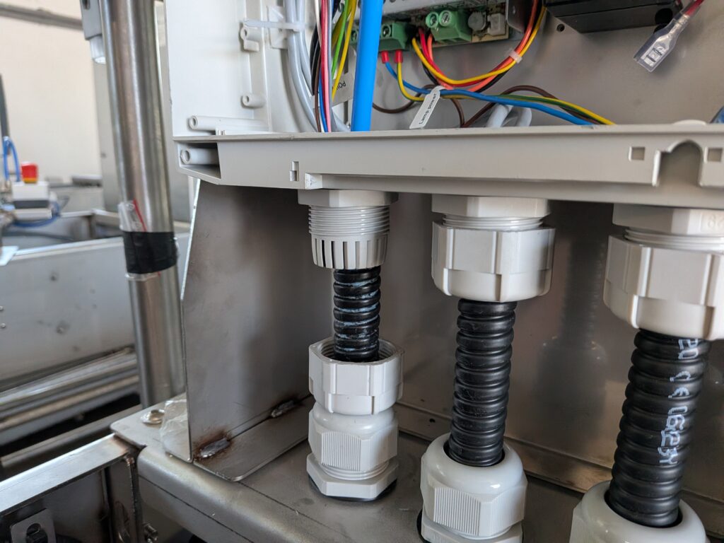
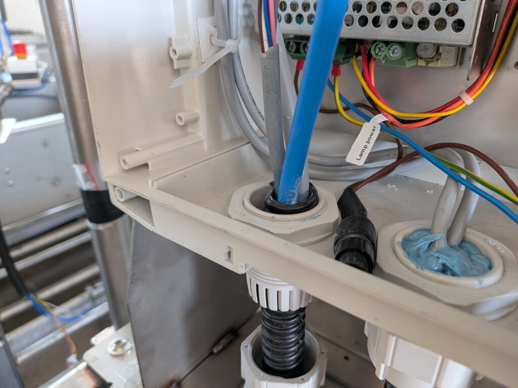
From the bottom of the controller housing, route the plugs, wires, and the pneumatic line through the lower cable gland.
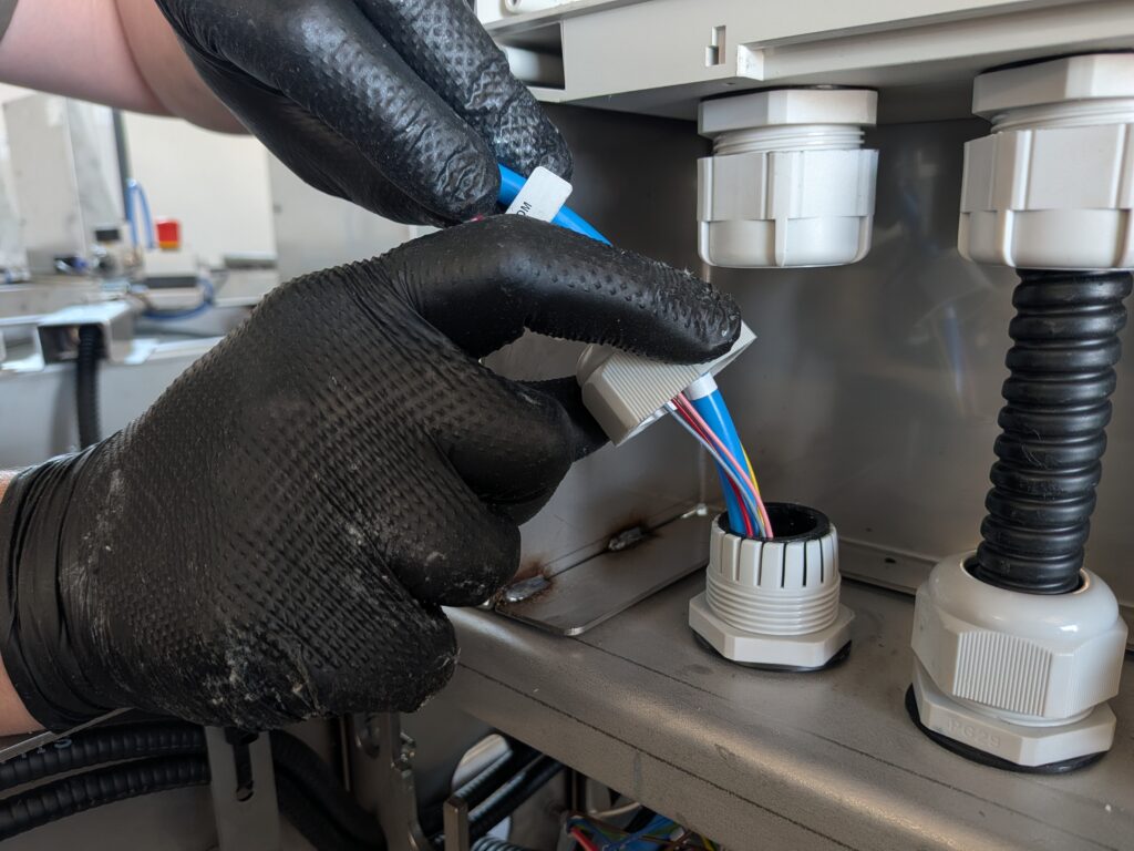
4. Tightening the grout joint
After routing all the cables, tighten the cable gland nut.
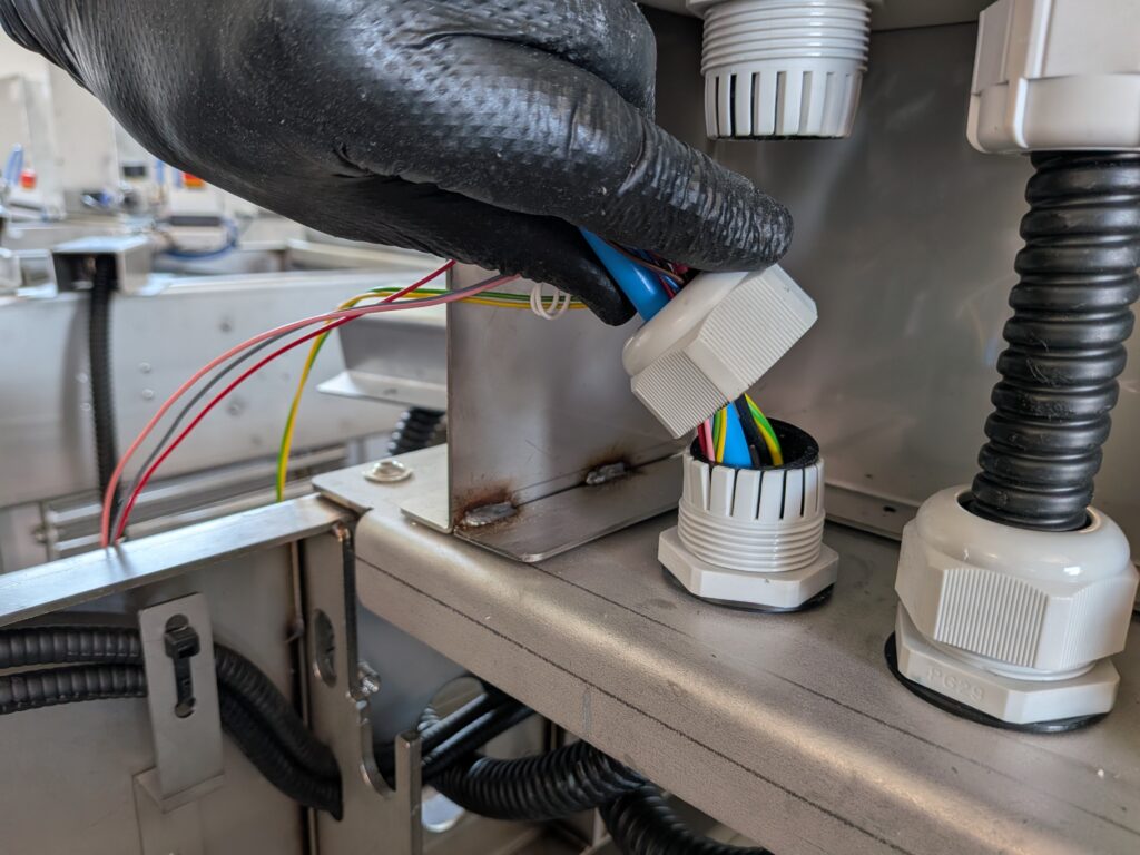
5. Upper culvert
The remaining cables should be routed through the upper cable gland.
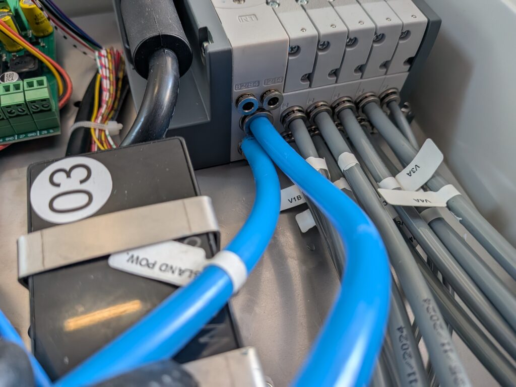
6. Connecting the pneumatic hose
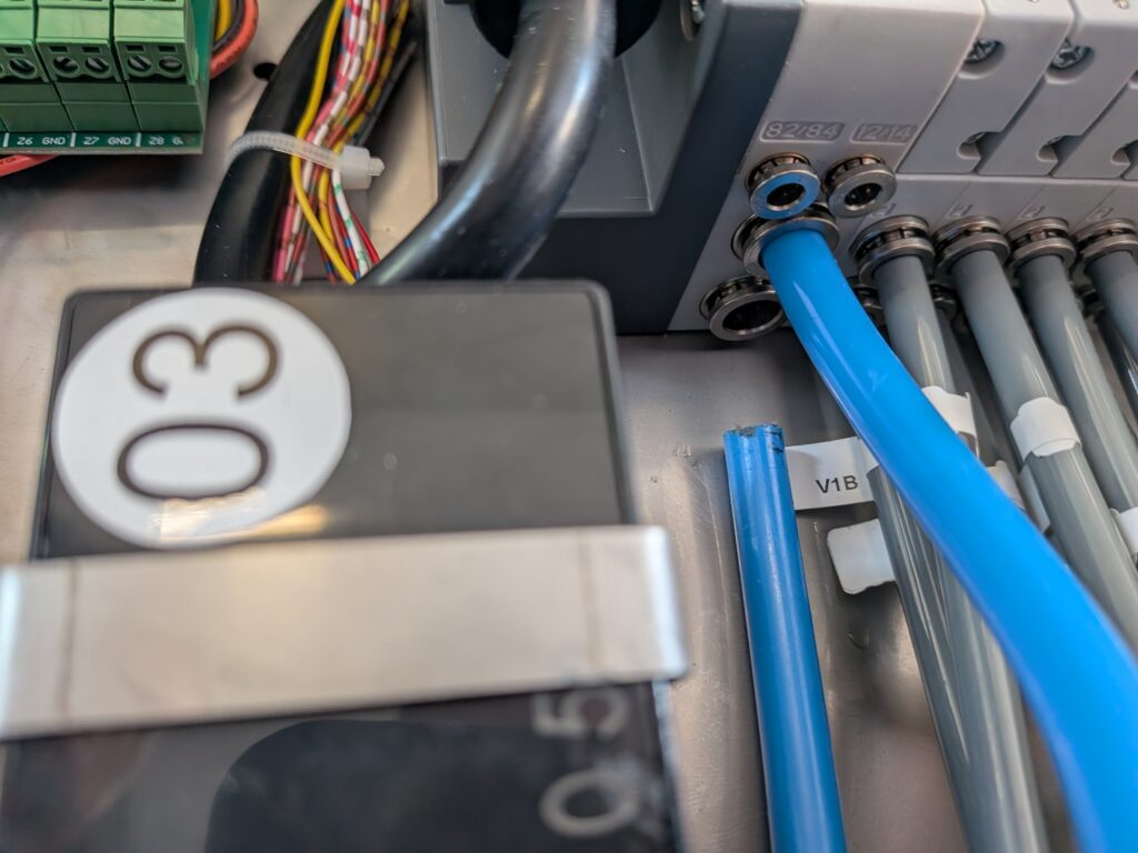
Connect the pneumatic hose to the valve manifold.
7. Connecting the Power Supply
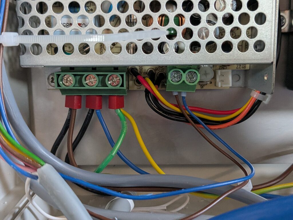
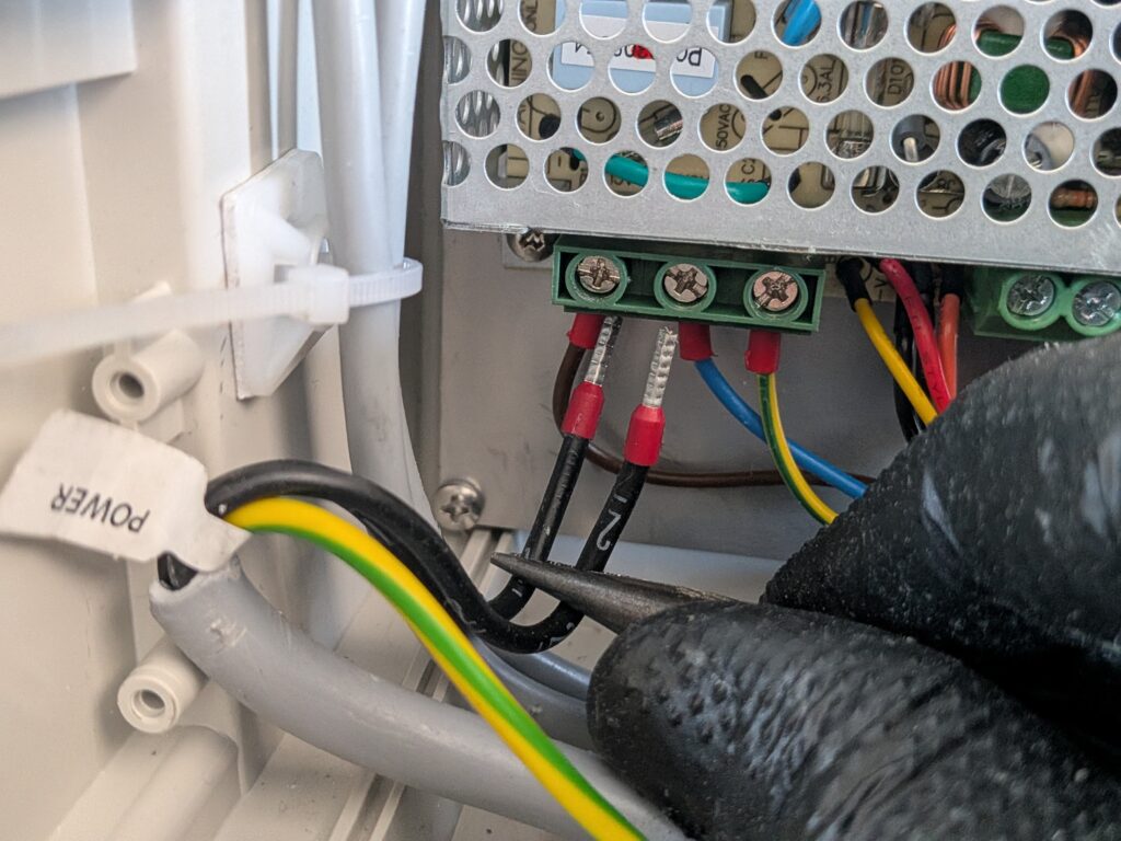
Connect the POWER plug to the power outlet according to the markings:
- 1 – phase (L)
- 2 – neutral wire (N)
- 3 – protective conductor (PE)
8. Connecting the S2 Connector
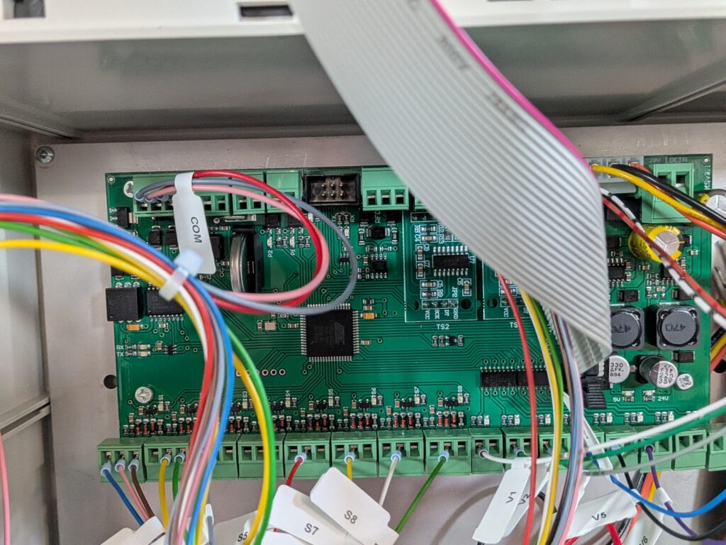
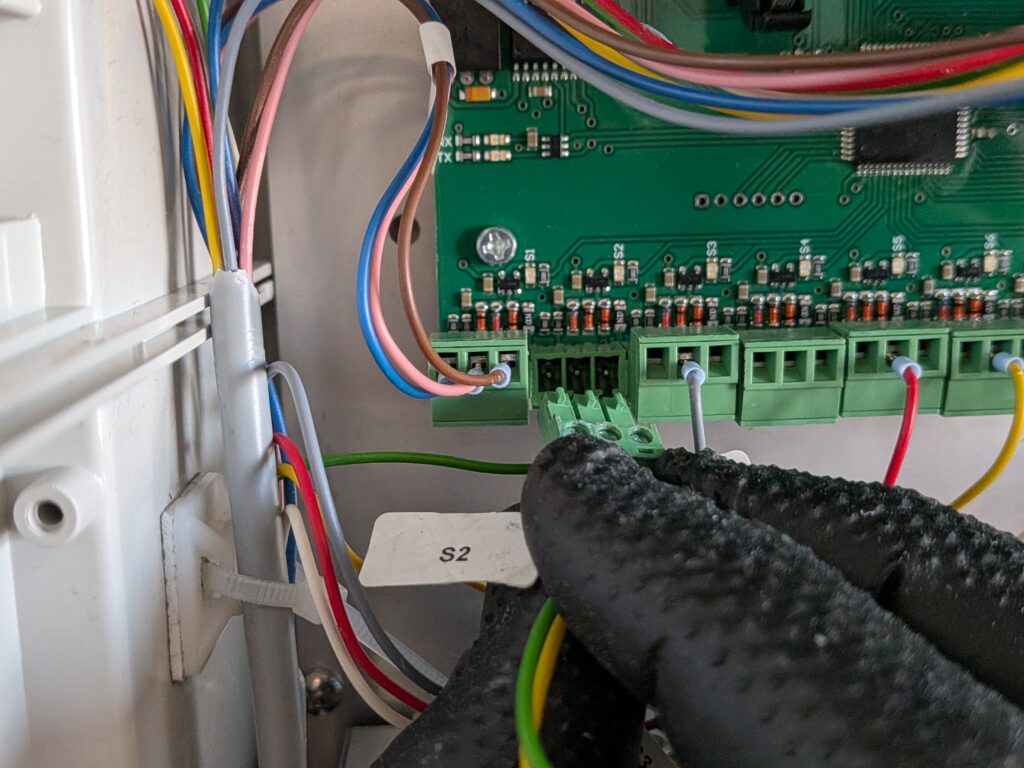
Plug S2 into the socket labeled S2.
9. Connecting the COM Connector
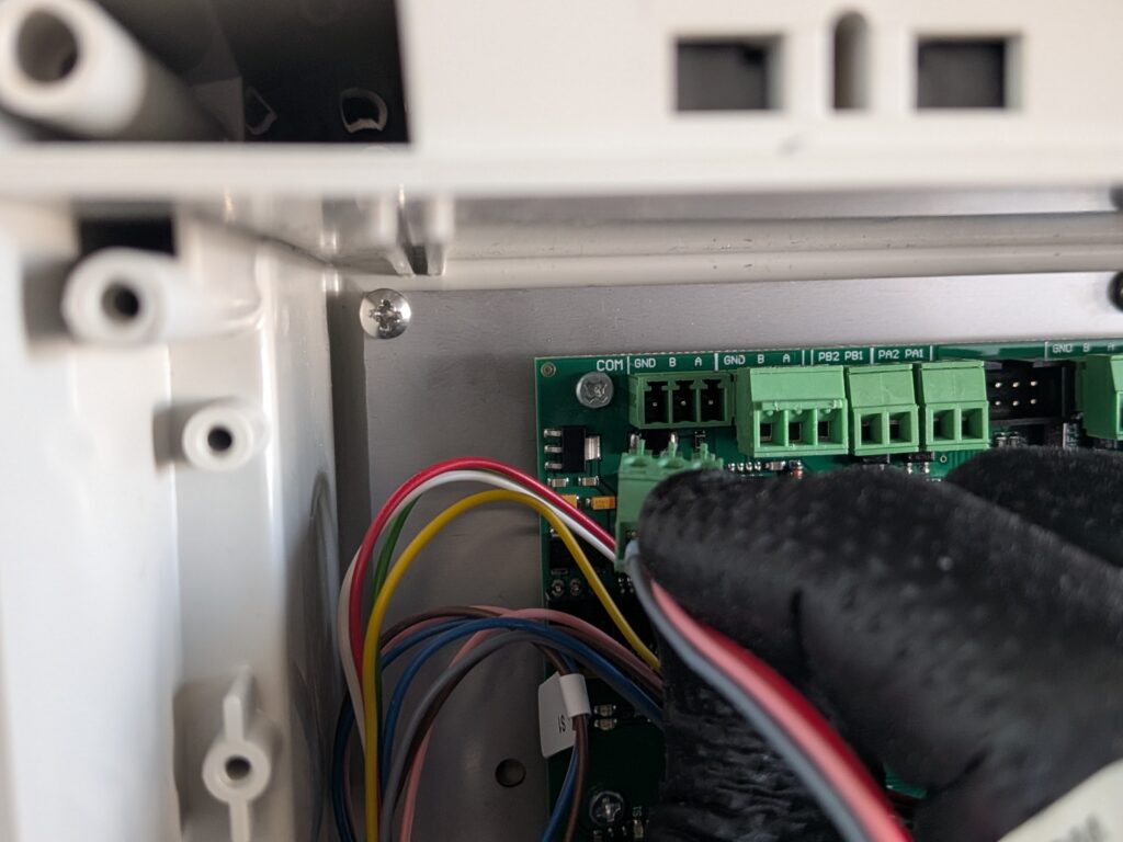
Plug the COM plug into the COM socket.
10. Verification of Proper Installation
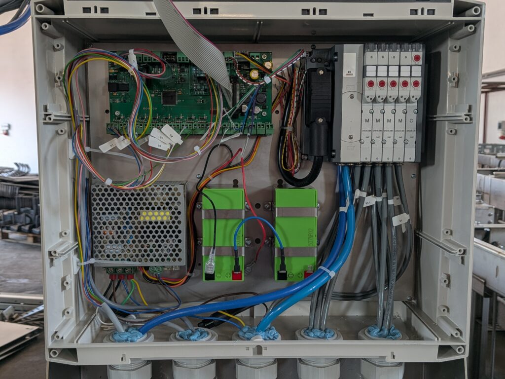
Once all the connections have been made, the controller should look like the one in the photo below.