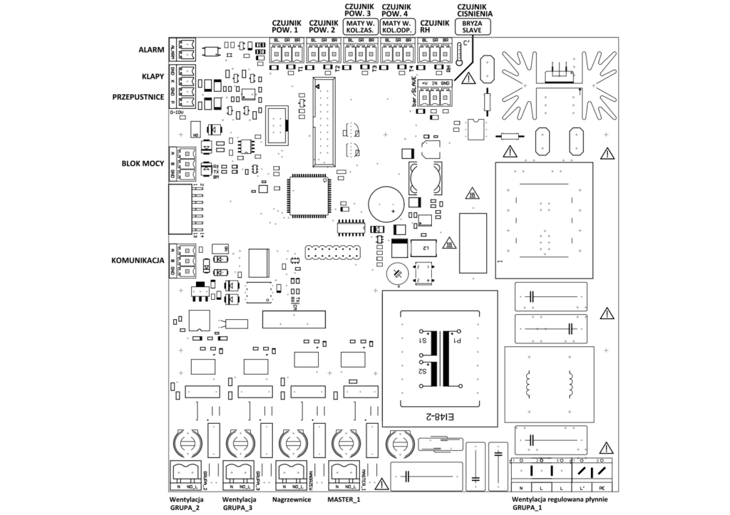
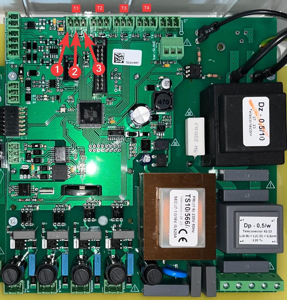
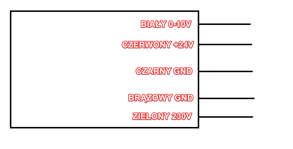
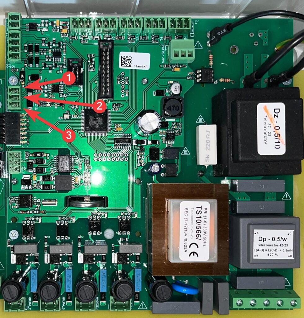
Schematic of the board
Technical data
| Type: | SK-2 10 A |
| L voltage Un | |
| Frequency | 50 Hz |
| Power consumption | <8 W |
| L’ adjustable current | |
| OUT 0-10V Analog signal | 0 – 10 V |
| Output 1 isolated | 230 V / 0.5 A |
| Output 2 isolated | 230 V / 0.5 A |
| Output 3 isolated | 230 V / 0.5 A |
| Output 4 isolated | 230 V / 0.5 A |
| Isolated alarm | 12 V / 0.2 A |
| Delayed protection | 0.1 A / 250 V |
- Enclosure protection type IP54
- Mains voltage 1~230 V (-15% / +10%), 50 Hz
- Output voltage steplessly adjustable 0 / 10 – 100% of the applied mains voltage
- Measurement range of the temperature sensor 0°C – 75°C
- Output 0 – 10 V, lmax 20 mA not short-circuit proof
- Maximum permissible ambient temperature of 40°C
- Minimum permissible ambient temperature -20°C
- Maximum permissible non-condensing relative humidity 85%
- Interference emission according to EN 61000-6-3
- Interference immunity in accordance with EN 61000-6-2
- Harmonic currents in accordance with EN 61000-6-2, up to a maximum current value of 4 A limits are maintained without limitation
Connecting the power supply of the large board
Connection to the mains is through the terminals: PE, L, N. The supply wire
connected to terminal L should be connected in the switchboard through
delayed installation circuit breaker S301 Cx , where x is the nominal current
of the circuit breaker, which should be equal to or slightly higher than twice
the nominal load current of the phase regulator. Note
that the line voltage must be within the permissible tolerance(see technical data). The line voltage must comply with DIN EN50160.

| 1 | N |
| 2 | L |
| 3 | L |
| 4 | L’ |
| 5 | PE |
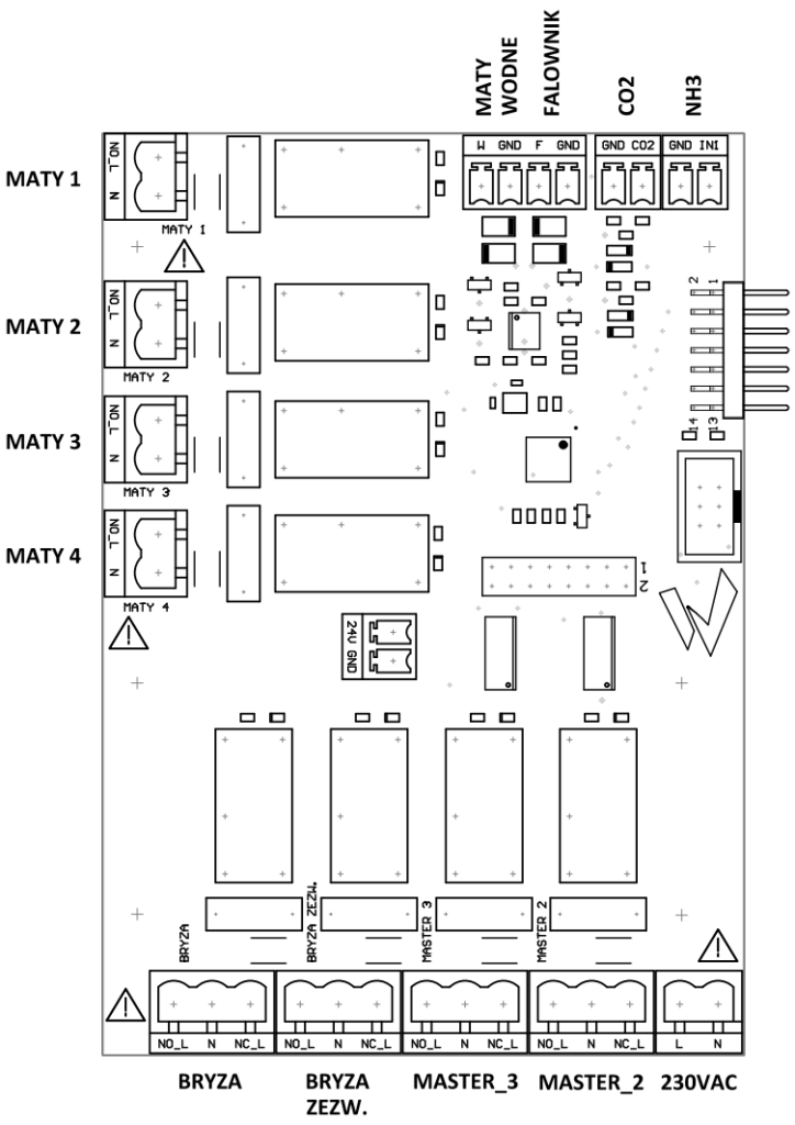
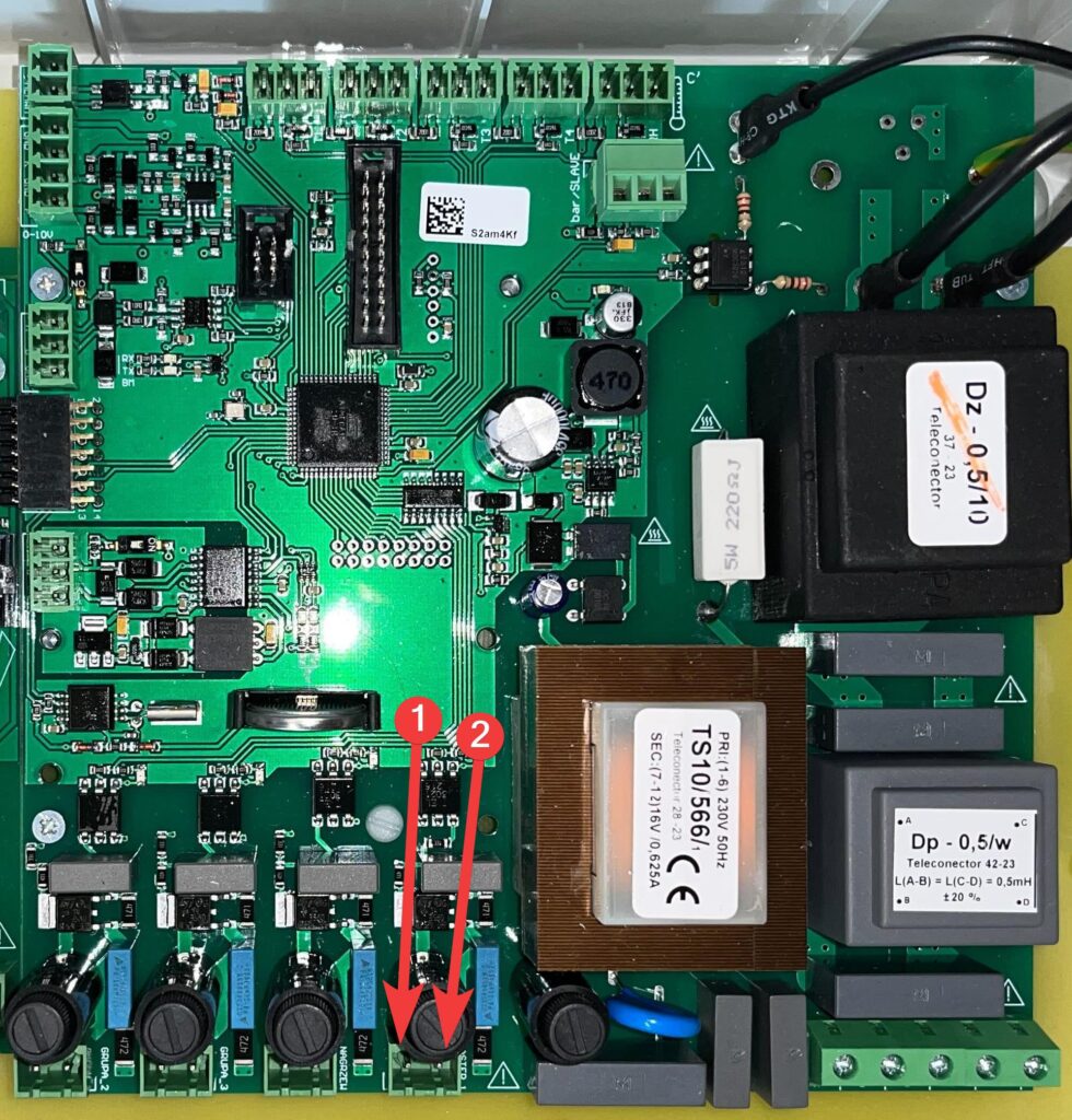
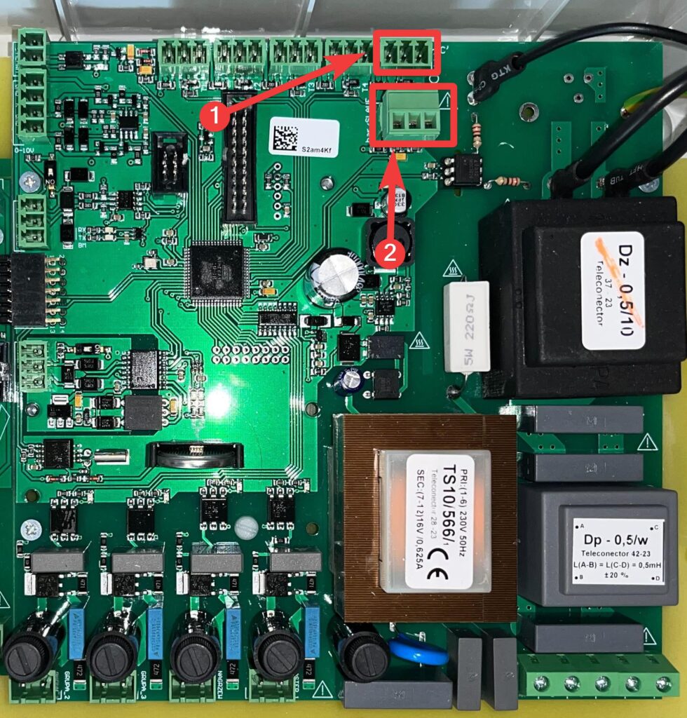
Connecting the power supply to the small board
The small board is powered by L and N cables connected to the marked locations.
| 1 | L |
| 2 | N |
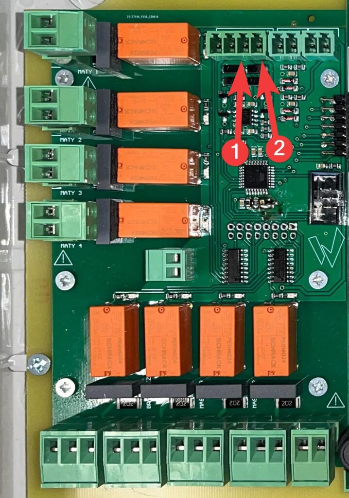
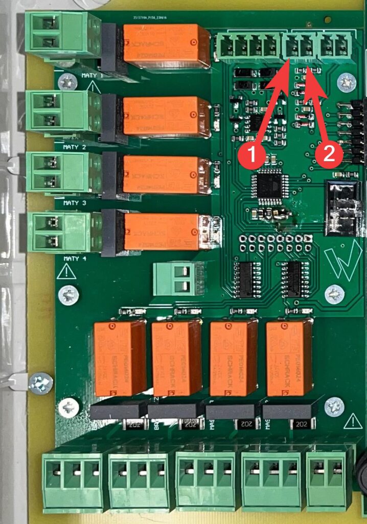
RS485 communication connection
The data cable is connected to terminals A, B and GND.
Do not connect the cable shield. Keep sufficient distance from
network cables and motor cables. The maximum cable length is 1000 m.
Recommended cable types:
- CAT5 / CAT7 cables
- J-Y (St)Y 2x2x0.6 (telephone cable)
- AWG22 (2×2 twisted pair)
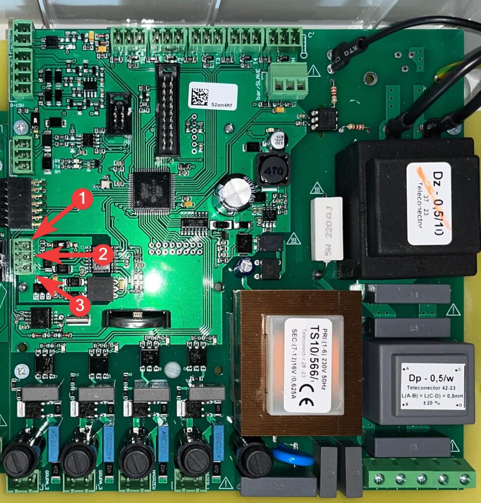
| 1 | A |
| 2 | B |
| 3 | GND |
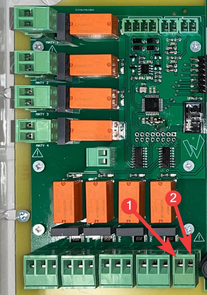
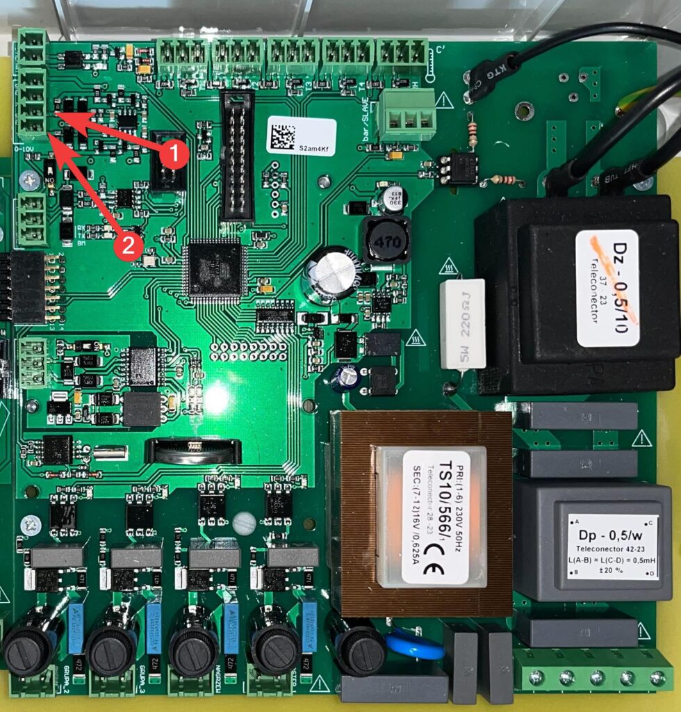
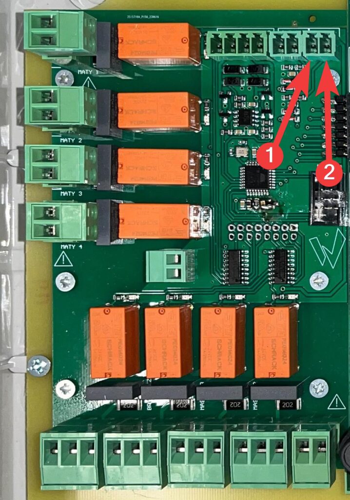
Termination of the communication line
If the SK-3 climate controller is the last device in the communication line, line termination must be enabled on it. This is done by setting the corresponding switch to ON, for RS485-1 it will be the switch marked [1], and for RS485-2 the switch marked [2].

Temperature sensors
Connecting
To avoid interference, keep the sensor wires a minimum distance of 0.5 m from the network wires and motor wires. The length of the sensor wires can be a maximum of 150 m, from 100 m must be shielded. In the case of
using shielded cable, the shield must be one-sided, that is, it must be
connected to the ground only on the controller side, by the shortest possible wire.
The device has 4 inputs for sensors (T1, T2, T3, T4). For proper operation of the controller it is sufficient to connect at least one sensor, because the controller calculates the average of the connected efficient sensors. It is advisable to connect
at least 3 sensors, for greater reliability, as damage
to sensor wires is a common cause of failure. If water mats are connected, water mat temperature sensors should be connected to sensor inputs T3 and T4.
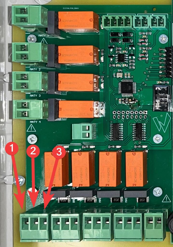
Connect the power supply to BL, the signal to GR, and the ground to BR.
| 1 | BL |
| 2 | GR |
| 3 | BR |
Temperature alarms
The climate controller has the ability to report 3 different alarms depending
on the measured temperature.
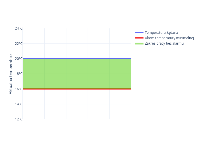
Minimum temperature alarm
This alarm will be reported when the temperature measured by the controller is less than the desired temperature by the number of degrees set by the minimum alarm temperature deviation parameter. If the deviation is set to 4°C and the desired temperature is 20°C, the alarm will be reported when the controller reads 16°C.
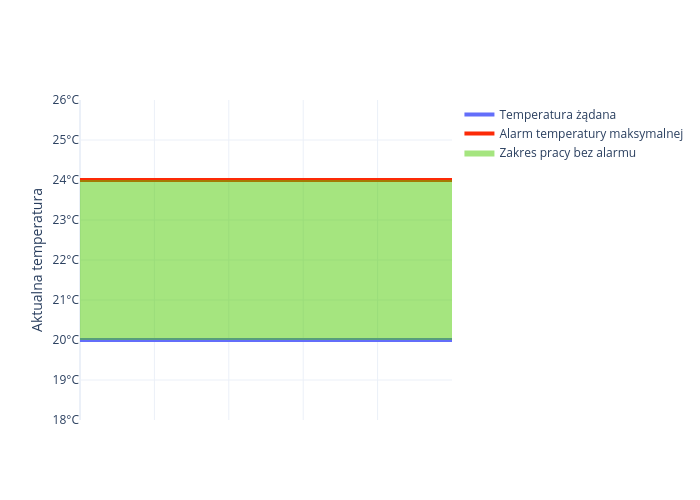
Maximum temperature alarm
This alarm will be reported when the temperature measured by the controller is greater than the desired temperature by the number of degrees set by the maximum alarm temperature deviation parameter. If the deviation is set to 4°C,
and the desired temperature is 20°C then the alarm will be reported when the controller
reads 24°C.
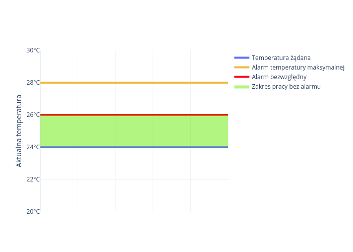
Absolute alert
This alarm will be reported when the temperature measured by the controller is greater than the temperature set by the absolute alarm parameter. The alarm is independent of the desired temperature and will always be reported when too much temperature is detected. If you set the absolute alarm threshold to 26°C then it will be reported regardless of whether the maximum temperature alarm deviation is set so that the maximum temperature alarm is not reported at this temperature.
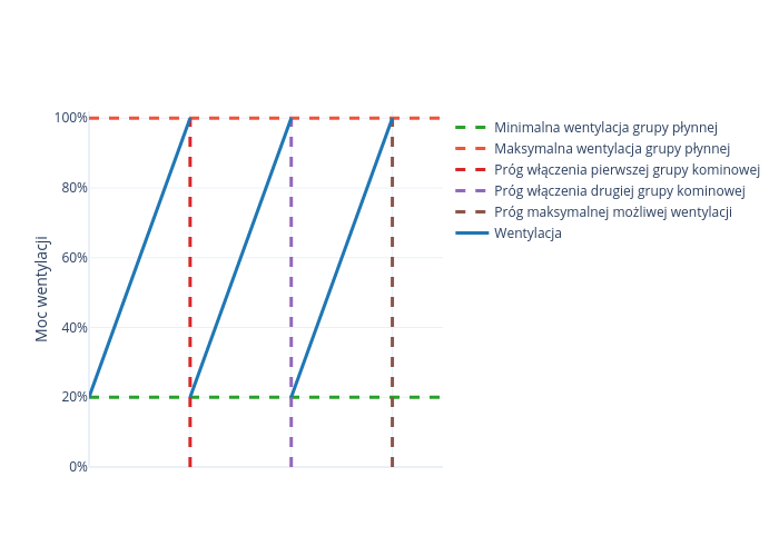
Ventilation
Continuously adjustable ventilation
The climate controller smoothly regulates ventilation, this involves smoothly adjusting the chimney fan from 0 – 100% and switching on the corresponding chimney groups when 100% is reached. If the controller has ventilation disabled then the ventilation will never go below the minimum ventilation. When the smooth group reaches 100% ventilation, the first chimney group is switched on, and the smooth group returns to minimum ventilation. If the fluid group reaches 100% again, the second stack group is turned on, and the fluid group’s ventilation returns to minimum ventilation.
If fewer chimney groups are connected, or if a liquid group without chimney groups is connected, then fewer chimney groups will turn on accordingly.
Inverter-controlled infinitely variable ventilation control
Liquid group ventilation can be controlled by connecting an inverter to the climate controller. The advantage of such a solution is to reduce the amount of electricity consumed.
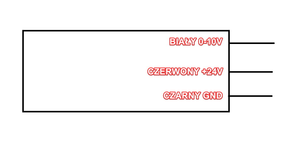
Connecting the inverter
Connect the power supply to the inverter under F, and the ground under GND.
| 1 | F |
| 2 | GND |
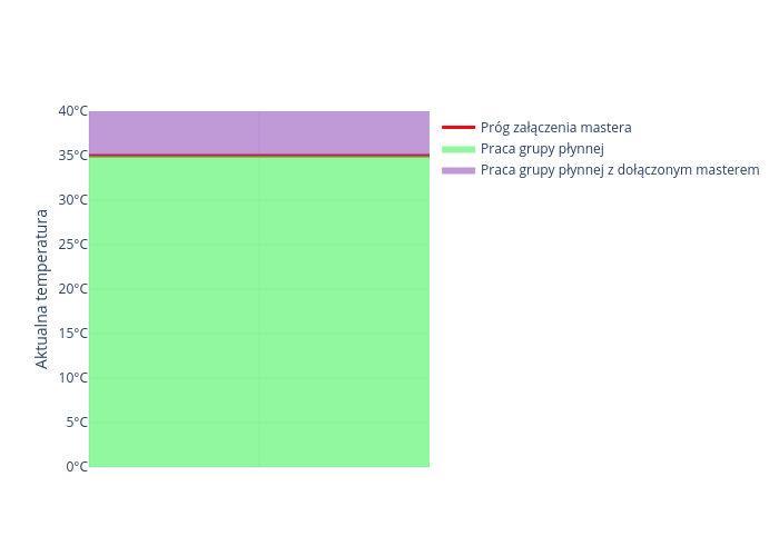
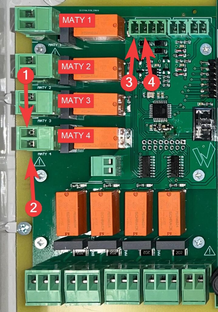
Mastery
The masters turn on independently of the ventilation of the fluid group, if the temperature threshold of any master is exceeded then the ventilation of the fluid group is set to minimum, and the master whose temperature threshold was exceeded is turned on.
Connecting
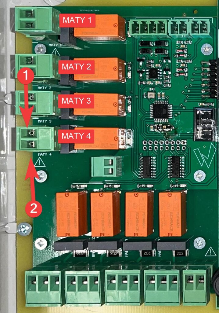
The first master is connected to the large board, the neutral is connected under N, and the power supply is connected under NO_L.
| 1 | N |
| 2 | NO_L |
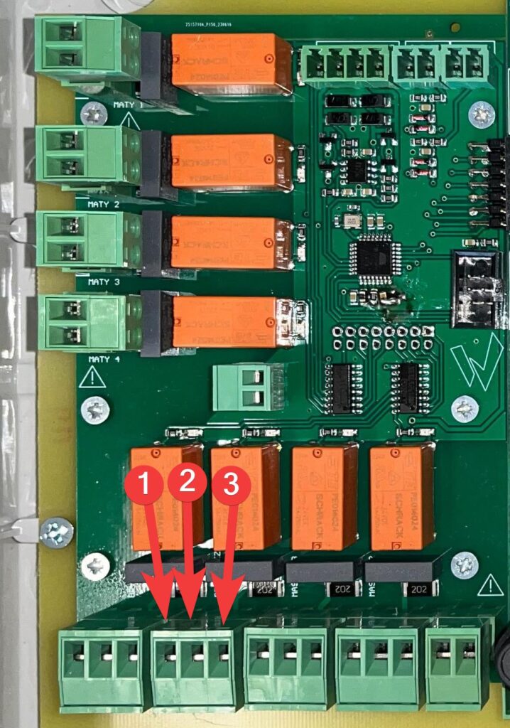
The other two masters can be connected to a smaller board. Depending on
what state you want the masters to be in, connect their power supply to either NO_L, or NC_L. Neutral connect under N.
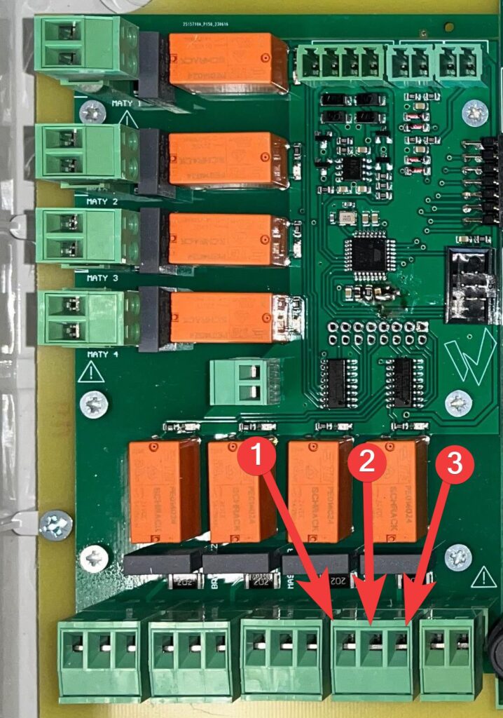
| 1 | NO_L |
| 2 | N |
| 3 | NC_L |
Master on temperature
The master will turn on only when a specific temperature is reached. Once the master falls below the set temperature threshold, it will stop operating in the smooth group. A different switch-on threshold can be set for each master.
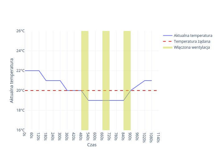
Venting
If intermittent operation has been enabled in the climate controller configuration, then
when the measured temperature falls below the desired temperature, ventilation will be activated. Venting is a ventilation mode that involves cycling ventilation on and off according to the set ventilation power, operating time and intermittent time.
Flaps
Vacuum setting
Setting the vacuum is based on setting the appropriate control voltages of the inlet dampers actuator for the selected ventilation intensities. The controller switches on the selected ventilation intensity sequentially, starting from zero to 100% chimney plus 3 masters, informs what it has switched on, and the installer’s task is to set such an opening of the inlet dampers to obtain the appropriate negative pressure in the room. When doing so, use a vacuum gauge or observe the precipitation of water mist when the frosty inlet air mixes with the moist air in the room.
Connecting
The unshielded flap control cable should be connected to the K (white cable) and GND (brown cable) terminals.

| 1 | GND |
| 2 | K |
Dampers
Connecting
The unshielded throttle control cable should be connected to the P (white cable) and GND (black cable) terminals.
| 1 | GND |
| 2 | P |
Throttle opening time
If the liquid group chimneys are equipped with dampers with
electric actuators, the ventilation must start with a delay in relation to the opening
of the dampers so that the dampers have time to open. This time is usually set
to 30 sec. Setting this time affects intermittent operation. If you set
a large delay time, the operation and intermittent operation times will increase while maintaining their mutual ratio, which in turn depends on the actual ventilation being implemented.
Power block
Connecting
Connect the wire to terminals A, B and GND
| 1 | A |
| 2 | B |
| 3 | GND |
Description of operation
The power block is used to equalize the speed of the fans connected in relation to the speed of the fans connected to the BM-2D extension. Pressing the – or + buttons changes the speed in the controller, while the speed of the fans connected to the power block does not change. During this adjustment, the speed of the fans should be as low as possible.
Cooling
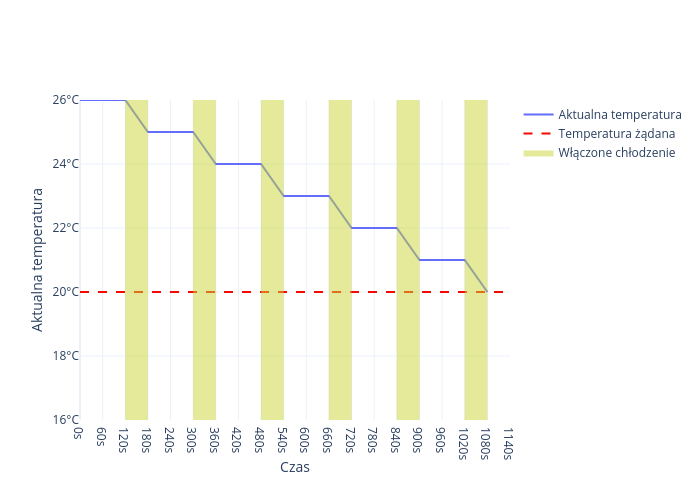
Cooling description
The cooling menu consists of such parameters as: switching on temperature,
working time, break time, maximum humidity, minimum pressure,
maximum pressure. The working time and break time should be selected so that there is no excessive
increase in humidity. Typically, the following is used: working time = 60 seconds and
break time = 120 seconds. If the switch-on temperature is set to 26°C, and a temperature greater than or equal to this value is measured, the controller will start cooling until the room temperature reaches the desired temperature.
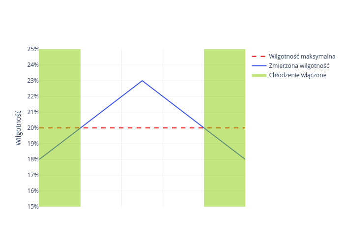
The next parameter is the maximum humidity. It is possible, but not recommended, to work with a non-functioning humidity sensor. For this purpose, enter the value
100%. If the maximum humidity is set to 20%, and the measured humidity
in the room is higher than it, the cooling will not be turned on until
humidity drops below the specified value.
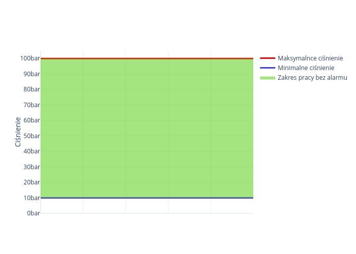
The next parameters are minimum pressure and maximum pressure. The
minimum pressure should be entered slightly lower than that appearing during operation
and visible as the current pressure. If in operation the current pressure is lower
than the minimum pressure we have entered, it will
indicate a disturbance in operation, e.g. a water leak through a leak, a turned-off valve
on the pump supply, an interruption in the water supply, etc. Cooling operation will
be stopped. The maximum pressure should be entered slightly higher than that appearing
during normal operation and visible as the current pressure. If in
operation the current pressure is higher than the
maximum pressure we have entered, this will indicate a malfunctioning
solenoid valve, for example. Cooling operation will be stopped.
It is possible, but not recommended, to work with a non-functioning pressure sensor. You should
for this purpose enter the values: minimum pressure = 0 at. and maximum pressure
equal to 100 at. Sensor connection is described below. When the controller is
in the operating time or interval time setting, the current time
of the cooling cycle is displayed on the 2nd line, as well as information on which conditions that enable
cooling operation are met and which are not. The conditions are displayed from left to right in the order,
in which they appear in the menu and in which they are described above. T means,
that the condition is met and operation is possible N that it is not. The first T from the left
means that the current temperature is higher than the switch-on temperature and if
the other conditions are also met, switch-on will occur. The second T means,
that the current cycle time is lower than the operating time we have set and the
operating time is just running. The third T means that the current humidity is lower than the maximum humidity we entered
and the humidity condition is met. The fourth T
means that the current pressure is between the minimum and maximum pressures entered by
us and the pressure condition is also met.
If four T’s are displayed, the controller turns on the pump and solenoid valve. If
any of the conditions is not fulfilled, the following is displayed in the appropriate place
N, and cooling operation is stopped.
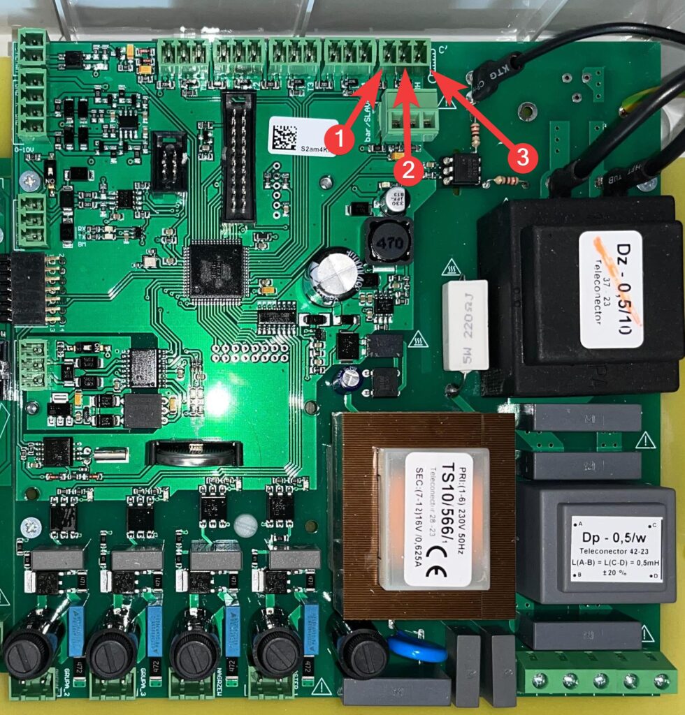
Cooling connection
All cooling system sensors are connected to the sensor inputs.
The humidity sensor is connected to the input described on the board as RH.
The pressure sensor is connected to the input described on the board as bar / SLAVE.
| 1 | RH |
| 2 | bar / SLAVE |
RH connection
Connect the power supply to the BL terminal, the signal to GR, and the ground to BR.
| 1 | BL |
| 2 | GR |
| 3 | BR |
Bar/SLAVE connection
Connect the power supply to the terminal described as +V, the signal to IN, and the ground to GND.
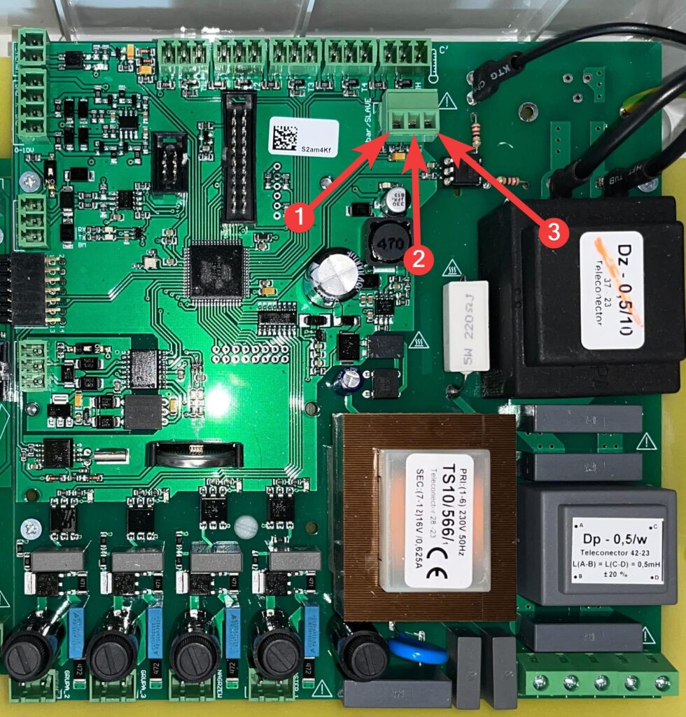
| 1 | +V |
| 2 | IN |
| 3 | GND |
Breeze
Depending on what you want the initial state of the breeze to be, hook the power supply up to NO_L if the default breeze is to be in the low state, or hook it up to NO_C if the breeze is to be
in the high state. Neutral hook it up to N.
| 1 | NO_L |
| 2 | N |
| 3 | NO_C |
Breeze permission
This input determines whether the breeze can be turned on. Depending on whether you want the input to default to a low state, plug the power supply into NO_L, or plug it into NO_C if the controller is to default to a high state. Neutral hook up to N.
| 1 | NO_L |
| 2 | N |
| 3 | NO_C |
Heaters
The heaters default to a low state, plug the power supply into NO_L,
a neutral into N.

| 1 | N |
| 2 | NO_L |
Setting the operating time and interval of the heaters
The operating and pause times of the heater should be selected so that the fluctuation
of temperature due to cyclic operation of the heaters is as small as possible. If
there is a start-up in the heaters, the operating time should be increased by this time. The time
of the interval should be selected so that, after its passing, there is a maximum
temperature indication on the corresponding sensor of this heater. In practice, usually
good results are: working time of 30 seconds and break time of 60 seconds.
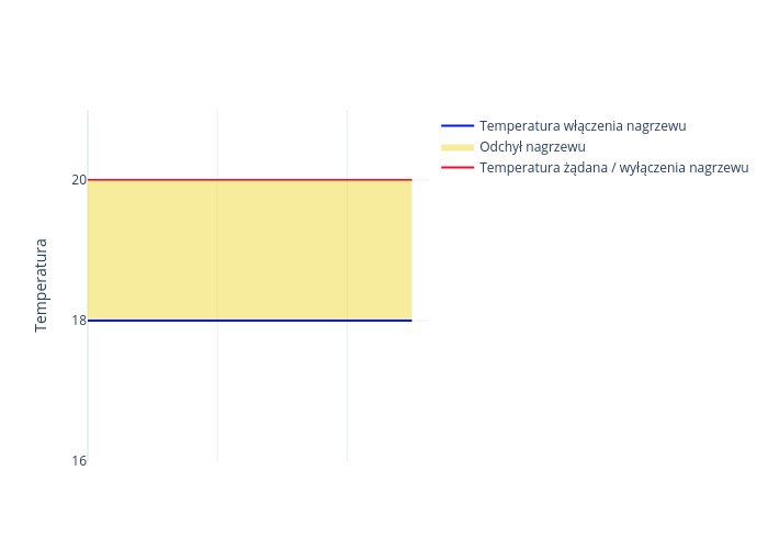
Heating deviation
This is a parameter that determines how much below the desired temperature
the temperature in the hall must fall in order for the heater to turn on. The heating is switched off,
when the temperature in the hall rises to the desired temperature.
So, by changing the desired temperature, we also change
the temperature by the same amount to turn the heating on and off, without changing the heating deviation.
Electric mats
Connection of electric mats
Electrical mats default to the low state. Connect the power supply to the NO_L terminal and the neutral to the N terminal.
| 1 | NO_L |
| 2 | N |
In the case of electric mats, we regulate the heating power without temperature control.
In view of this, the heating percentage must depend on:
- Temperature we want to get on the mat
- Temperature dependent on the day of the curve
- Room temperature
- Temperature read by the controller with air sensors
- Nominal power of the mat
There are mats with different wattages. Using power percentage calibration for
levels, we can set equal temperatures.
Mat calibration
(a) Preview of settings
Simultaneous on-screen preview of calibration settings of levels 0 and -2 for all
four mats.
(b) Calibration:
Level 0:
This involves setting the percentage of power at which the
mat we are setting will reach 39°C at a room temperature of 22°C. If we carry out this calibration
in conditions where it is impossible to get the
air temperature equal to 22°C, we aim to achieve a mat surface temperature 17°C
higher than the air temperature.
Level -2:
This involves setting the percentage of power at which the
mat we are setting will reach a temperature of 35°C at a room temperature of 22°C. If we carry out this calibration
in conditions where it is impossible to achieve a
air temperature of 22°C, we aim to achieve a mat surface temperature 13°C
higher than the air temperature.
Controlling the mats
a) according to the curve
b) according to level 0
c) according to level -2
When calibrating the levels, we must use the work according to the levels described
above. Because the calibration process involves temperature control
after the mat temperature has stabilized. We take temperature measurements of the mats
several times. The measurement is correct only when the temperature has not
changed since the previous measurement. Setting the following functions makes
the controller work even if you exit the menu. It is necessary to remember
to set the option of controlling the mats according to the curve again after calibration.
Water mats
Connection of water mats
Electrical mats default to the low state. Connect the power supply to the NO_L terminal, and the neutral to N. Connect the signal from the three-way valve control to W,
and ground to GND.
| 1 | NO_L |
| 2 | N |
| 3 | W |
| 4 | GND |
Parameters of water mats
Collector dynamics
If water mats are selected, enter how long it takes
for the temperature indicated by sensor T3 to stabilize, from the moment
the position of the three-way valve changes. This time depends on the distance of the
temperature sensor from the three-way valve, and the speed of the water flow.
The greater the distance, the longer the time, the faster the water flow, the shorter the time.
Entering too short a collector dynamics time causes unstable operation,
while too long causes the control to lag behind the changing
temperature of the hot water supplying the floor. The T3 sensor should be on the
pipe between the three-way valve and the supply manifold as close to the valve as possible,
so that the response time after a change in the valve setting is short. This will
allow the manifold dynamic time to be set short and ensure accurate and stable
operation of the control system.
Collector maximum temperature
To protect against the occurrence of too high a floor temperature
, the maximum collector temperature should be entered 2 to 6 °C higher
than the temperature you want to have on the floor. If we have a small temperature difference between the inflow and outflow
of the floor as a result of the intensive
water flow, then the entered value should be 2 degrees higher, if the flow is
small, then the difference is large and the entered value higher.
Resolution of valve voltage regulation
If the inflow manifold sensor is not located
directly behind the three-way valve, or the flow of water in the floor is too
slow, there may be instability in the operation of the controller. This manifests itself
by cyclic closing and opening of the three-way valve. To stabilize
the operation of the system, reduce the setting of “valve voltage resolution”
from the factory value of 100% to 25%, and if this does not help then even lower.
Instantaneous control factor
Proceed in the same way as setting the resolution of the valve voltage adjustment.
CO2 sensor
Sensor connection
We connect theCO2 sensor signal to the CO2 input, and ground to GND.
| 1 | GND |
| 2 | CO2 |
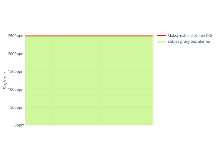
Sensor calibration
Too much carbon dioxide alarm
On the climate controller, set at which value the alarm for too much carbon dioxide concentration should be reported.
Minimum sensor value for minimum voltage
This is the value of the concentration of carbon dioxide in the air at which the sensor has a minimum voltage at the output. A further decrease in concentration does not cause a voltage drop
Maximum sensor value for maximum voltage
This is the value of the concentration of carbon dioxide in the air at which the sensor has a maximum voltage at the output. A further increase in concentration does not cause an increase in voltage.
NH3 sensor
Sensor connection
We connect the NH3 sensor signal to the NH3 input, and ground to GND.
| 1 | GND |
| 2 | NH3 |
Sensor calibration
Alarm of too high concentration of ammonia
On the climate controller, set at which value the alarm for too much ammonia concentration should be reported.

Minimum sensor value for minimum voltage
This is the value of the concentration of ammonia in the air at which the sensor has a minimum voltage at the output. A further decrease in concentration does not cause a voltage drop
Maximum sensor value for maximum voltage
This is the value of the concentration of ammonia in the air, at which the sensor has a maximum voltage at the output. A further increase in concentration does not cause an increase in voltage.