
1. General Information
The FarmWatch Pro control unit supports up to 8 digital inputs, designed to work with various types of sensors and external devices.
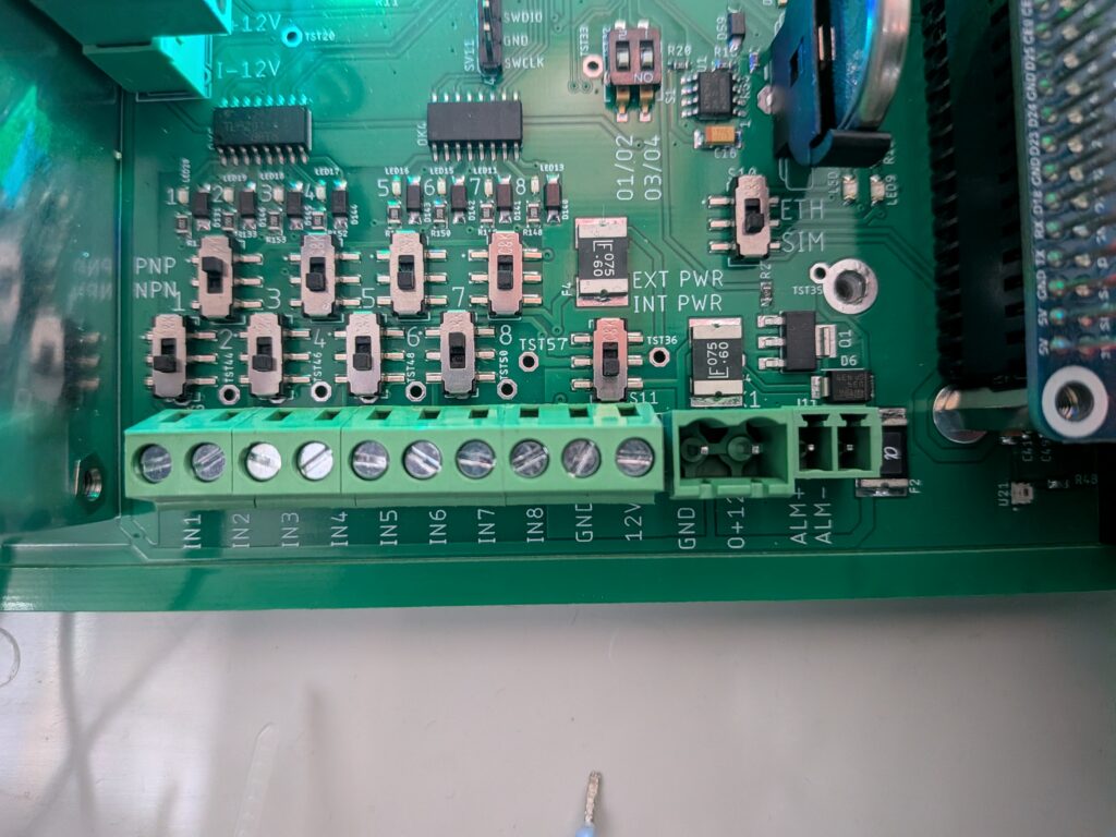
Each input can operate in one of two power modes:
- INT PWR (Internal Power) – the device is powered by the FarmWatch Pro control unit or by its own power source
- EXT PWR (External Power) – the device requires an external power supply, typically 24 V DC.
1.1 Operating Mode Configuration
Before connecting the device, determine how it will be powered and configure the input accordingly.
The mode is selected using a switch (slider) located next to the respective input.
There are two settings available:
- INT PWR – for devices powered by the control panel or equipped with their own 12V DC power source.
- EXT PWR – for devices requiring an external 24 V DC power supply.
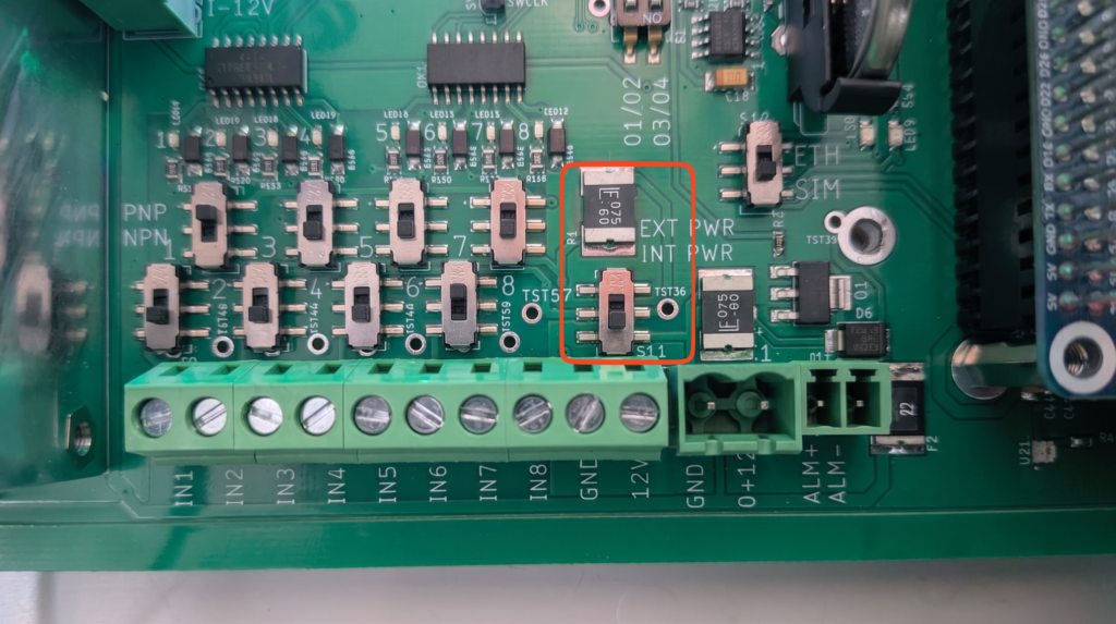
NOTE
Incorrect switch settings or improper wiring may cause the device to malfunction and, in extreme cases, may result in damage to the device. Always review the sensor manufacturer’s documentation before connecting the device.
1.2 Connecting INT PWR Devices
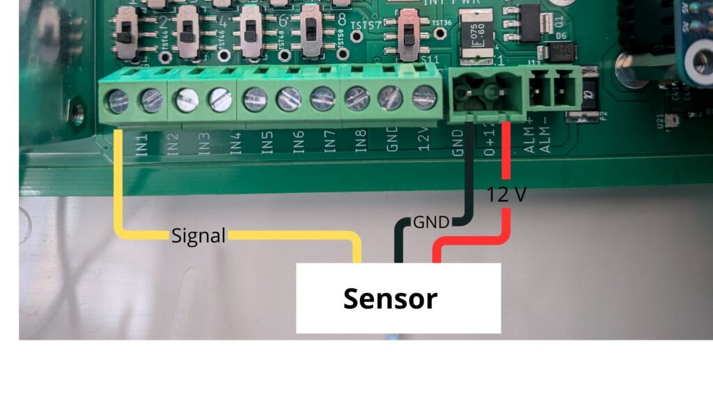
For devices operating in INT PWR mode, make the following connections:
- Connect the GND wire to the GND terminal.
- Connect the power cord to the power terminal located on the left side of the connector.
- Connect the signal cable to the appropriate IN1–IN8 input.
1.3 Connecting EXT PWR Devices
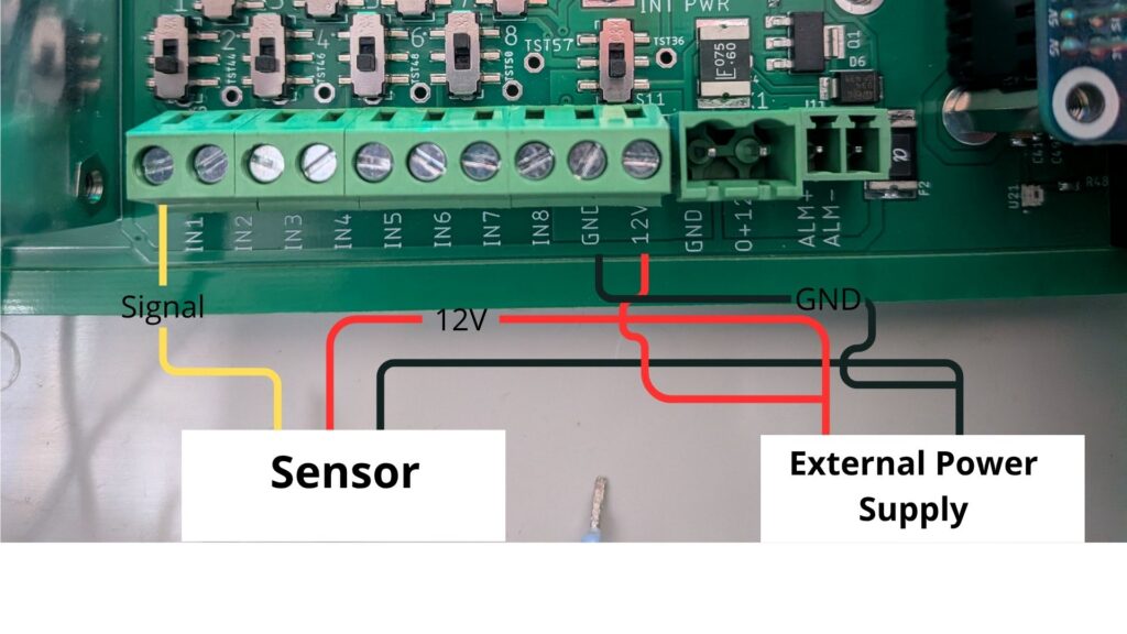
For devices that require an external power supply, do the following:
- Connect the signal cable to the appropriate IN1–IN8 input.
- Connect an external 24 V DC power source to the dedicated power connector.
1.4 Types of Input Signals
FarmWatch Pro is compatible with devices that use the two most popular digital output standards.
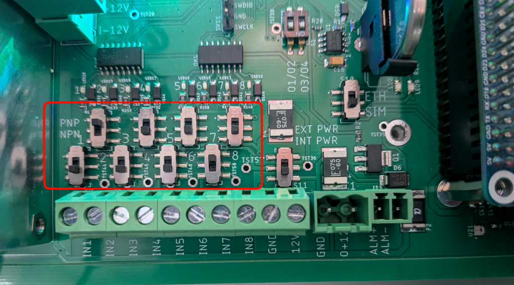
PNP (positive output)
Once the sensor is activated, a positive supply voltage (usually +24 V DC) appears at the output.
NPN (open-collector output)
When the sensor is activated, the output is shorted to ground (GND / 0 V).
Check the device manufacturer’s technical documentation for information on the sensor’s output type.


