This article describes all the steps you need to follow to properly wire up dispensers to Connector and Connector Extension.
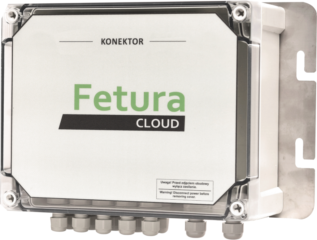
Connector
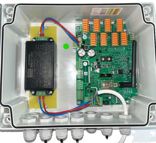
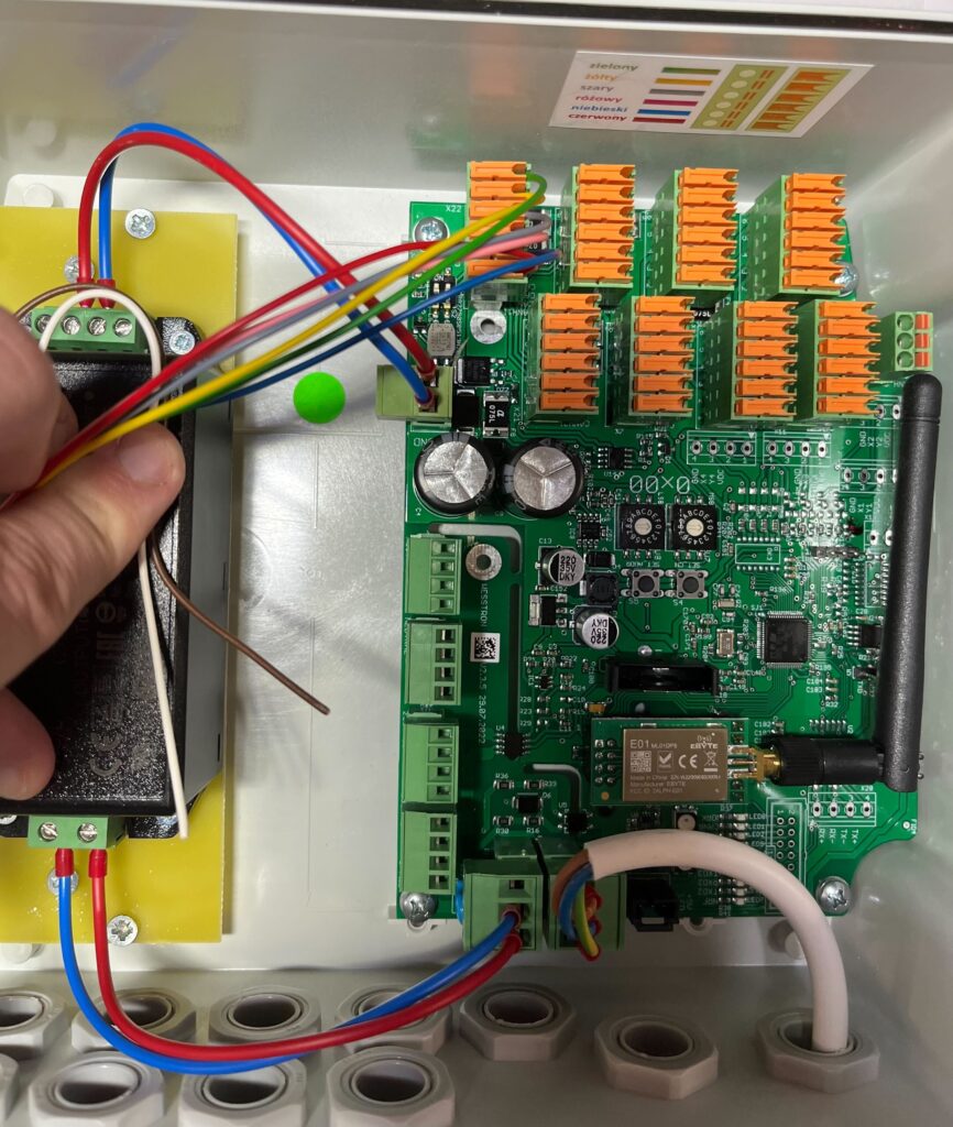
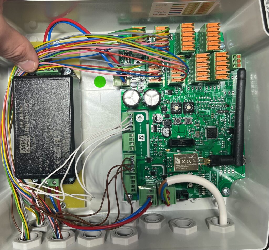
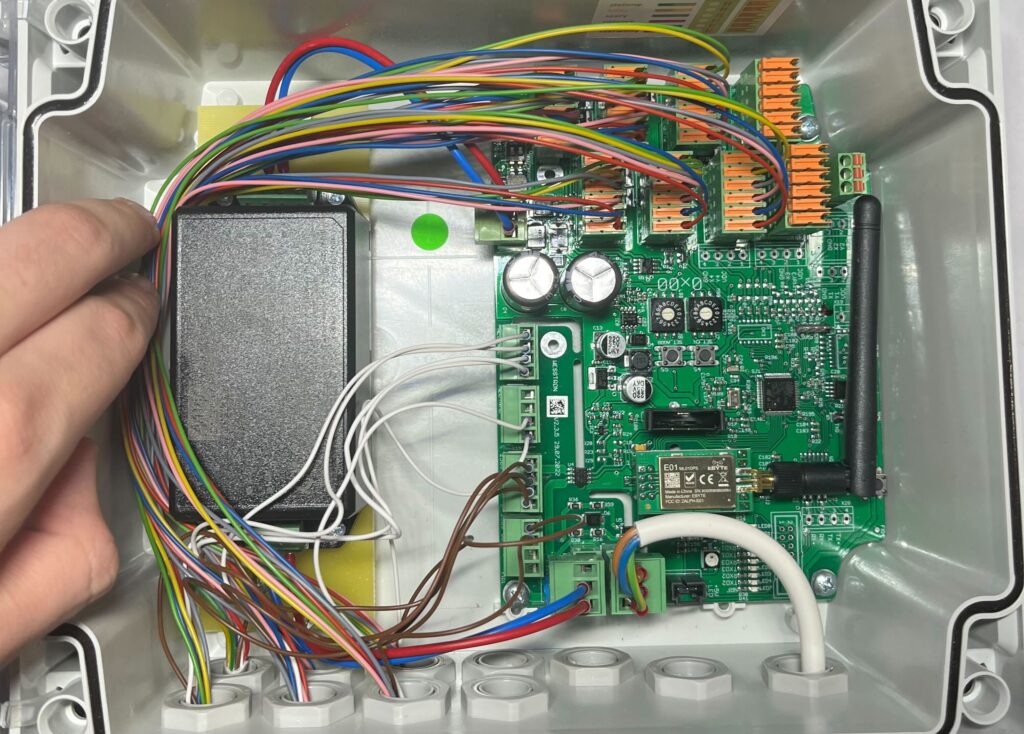
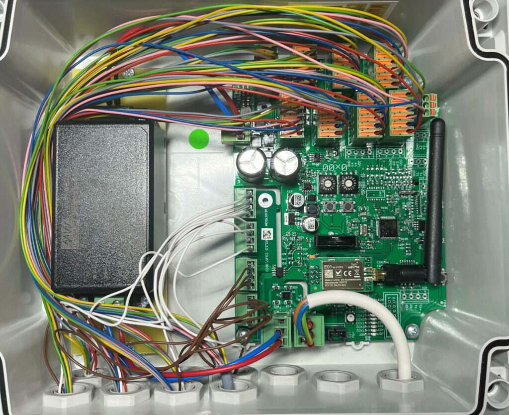
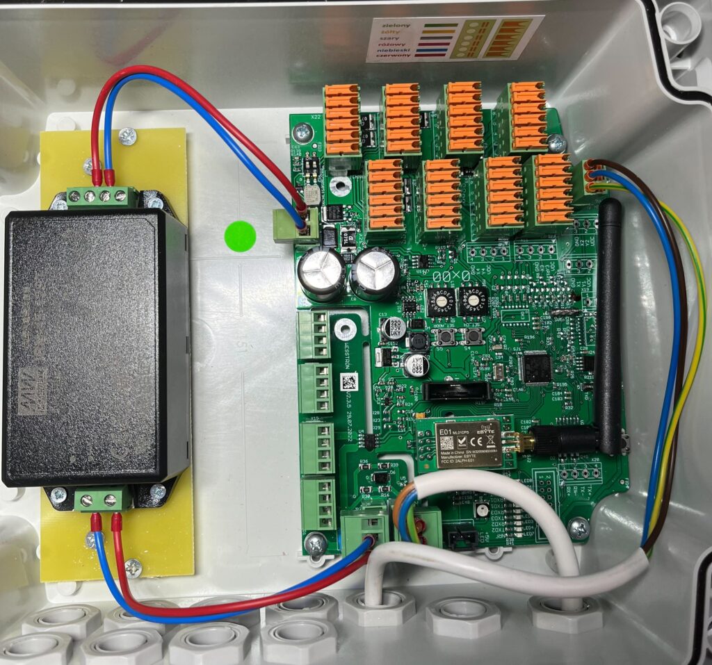
Connector in the factory state has the main power supply and DC power supply connected and is prepared for wiring dispensers.
Wiring a single dispenser
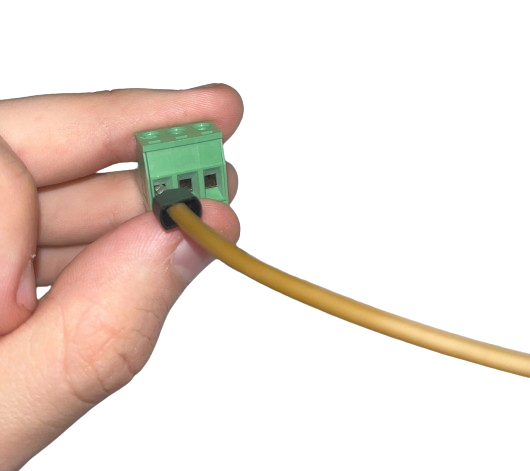
Enter the cable from the dispenser number 1 into the housing of the Connector and remove 35-40 cm of insulation.
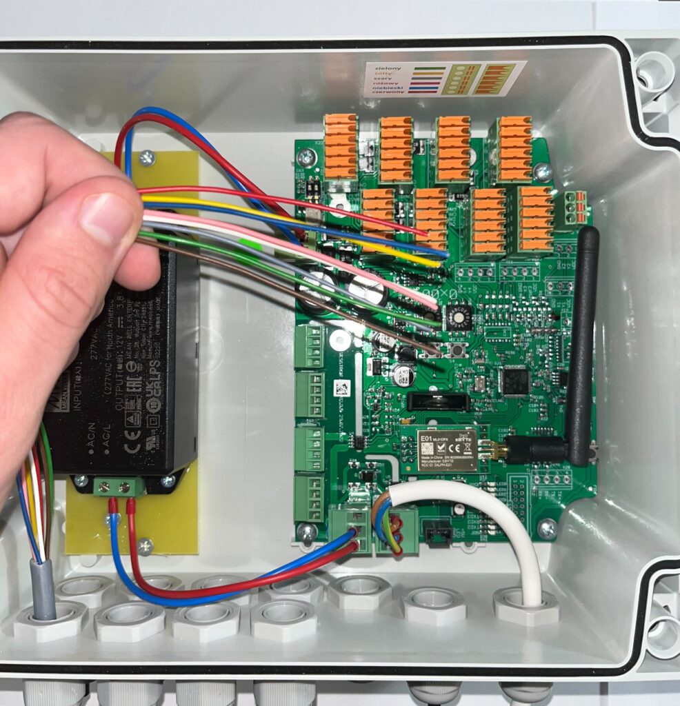
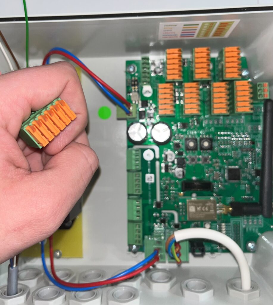
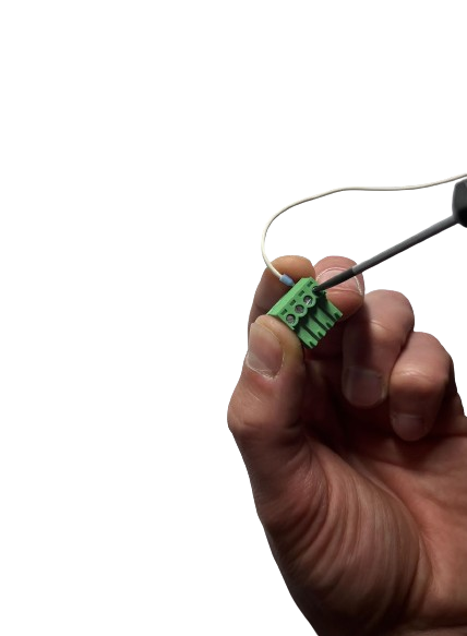
Remove the plug from dispenser number 1
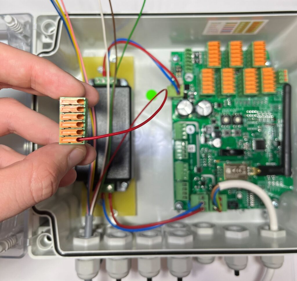
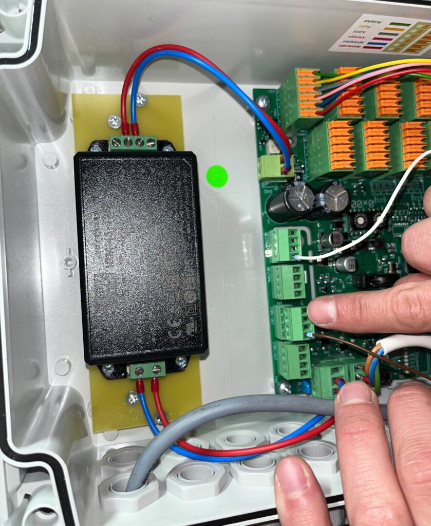
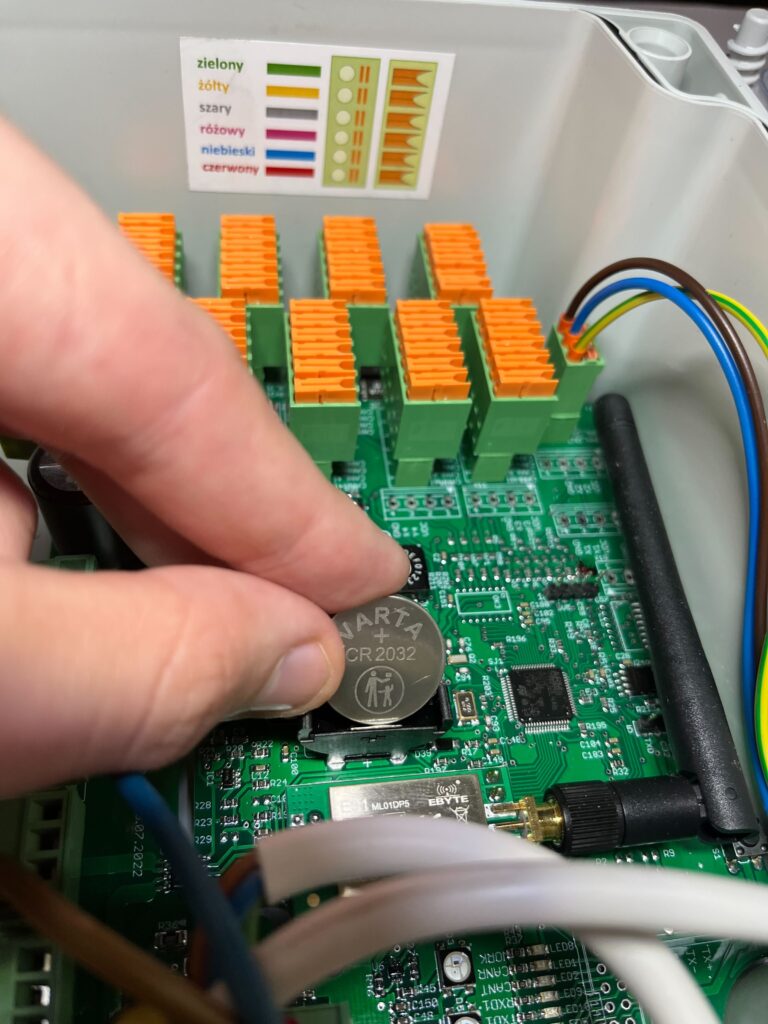
Connect the wires according to the color scheme inside the case.
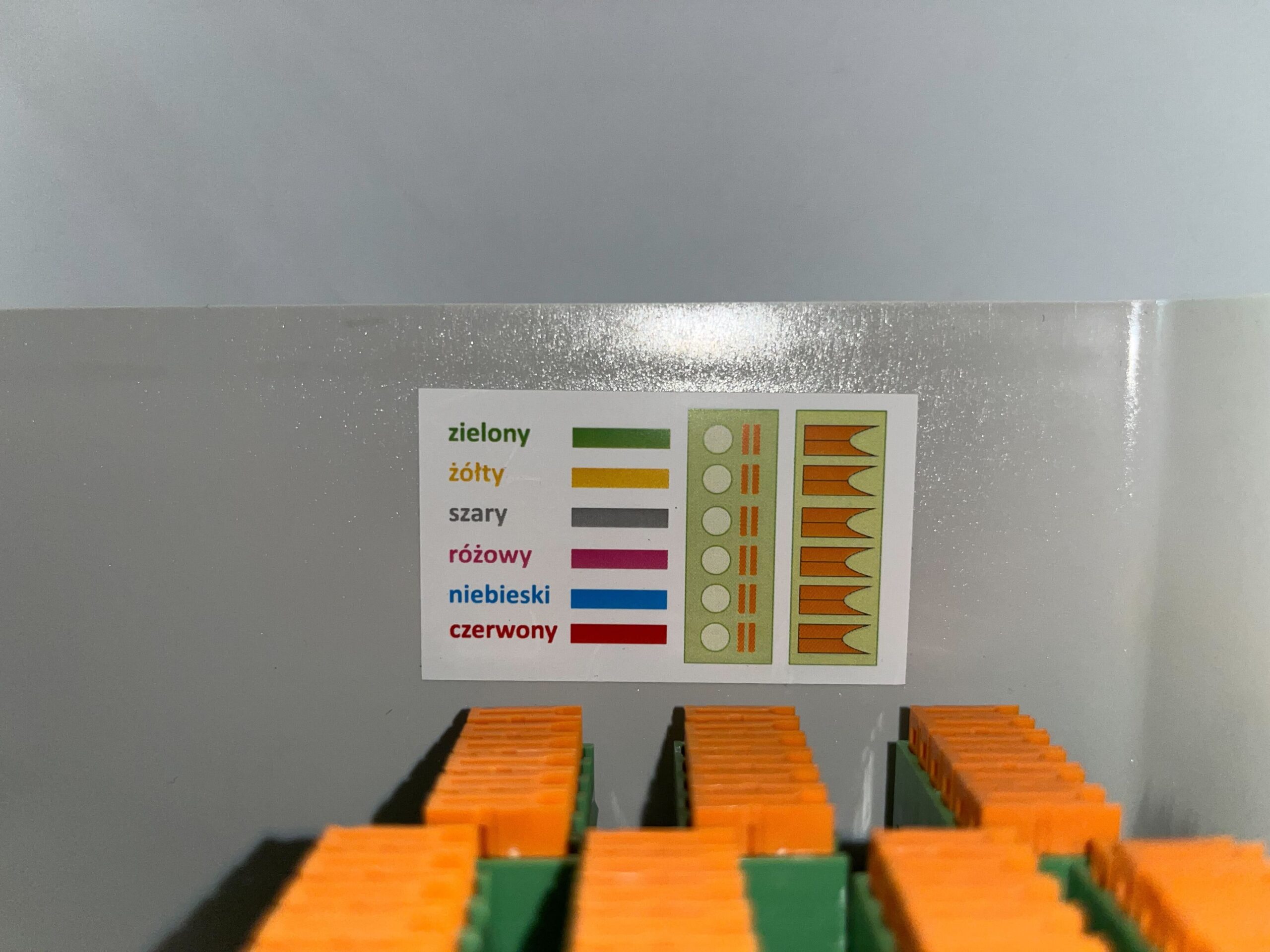
Insert the red wire into the plug and lightly tighten the terminal.
Insert the blue wire and lightly tighten the clamp.
Insert the pink wire and lightly tighten the clamp.
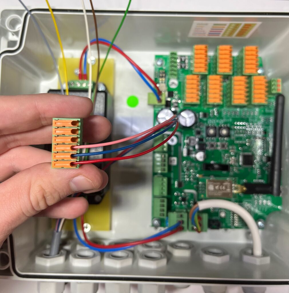
Insert the gray wire and lightly tighten the clamp.
Insert the yellow wire and lightly tighten the clamp.
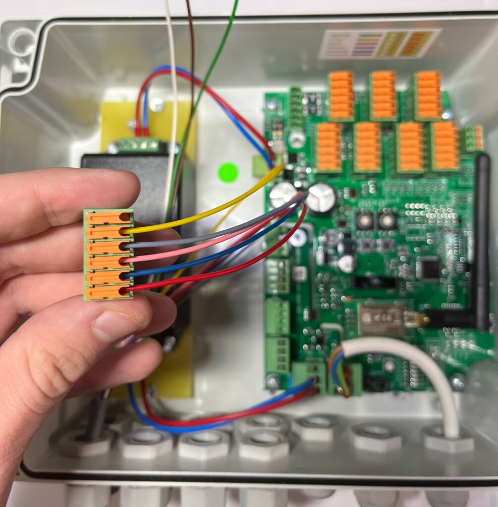
Insert the green wire and lightly tighten the clamp.
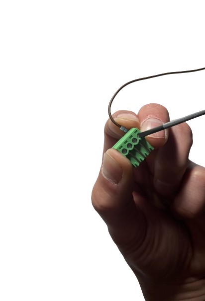
Insert the plug into the socket from dispenser number 1
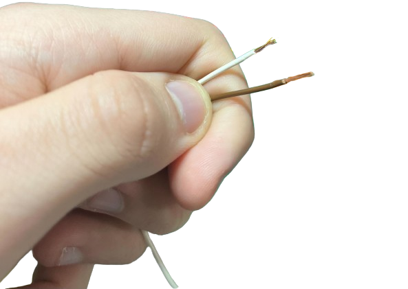
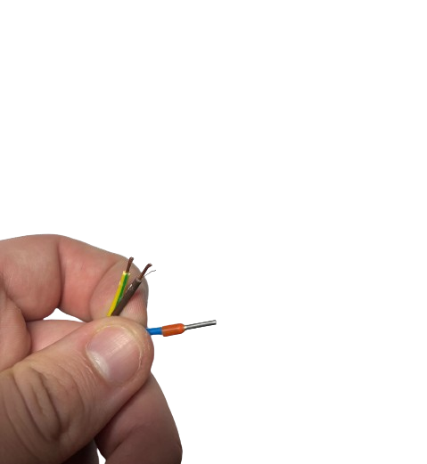
Remove the insulation from the white and brown wires.
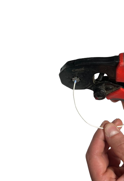
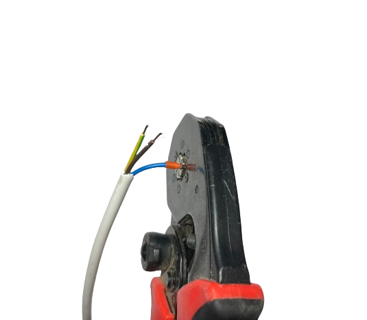
Apply and tighten the collet to the white wire.
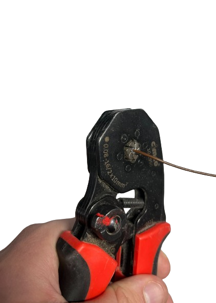
Apply and tighten the collet to the brown wire.
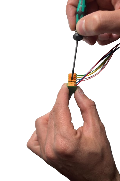
Remove the plug for connecting the white wire, unscrew the screw so that the wire can be inserted, then insert it and tighten the screw.
Remove the plug for connecting the brown wire, loosen the screw so that the wire can be inserted, then insert it and tighten the screw.
Tighten the terminals at the plug from dispenser number 1 with a screwdriver.
Insert the plug with the white wire (neutral wire)
Insert the plug with the brown wire (phase wire)
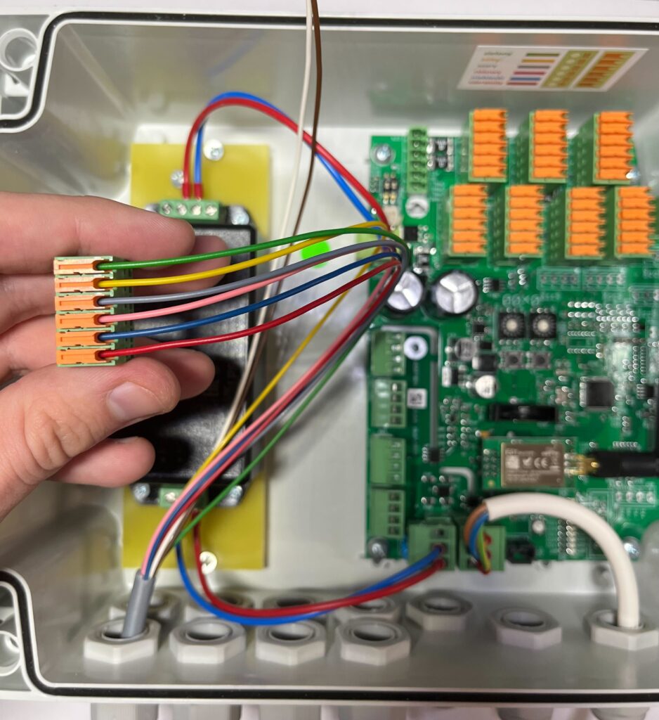
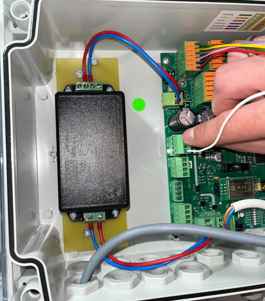
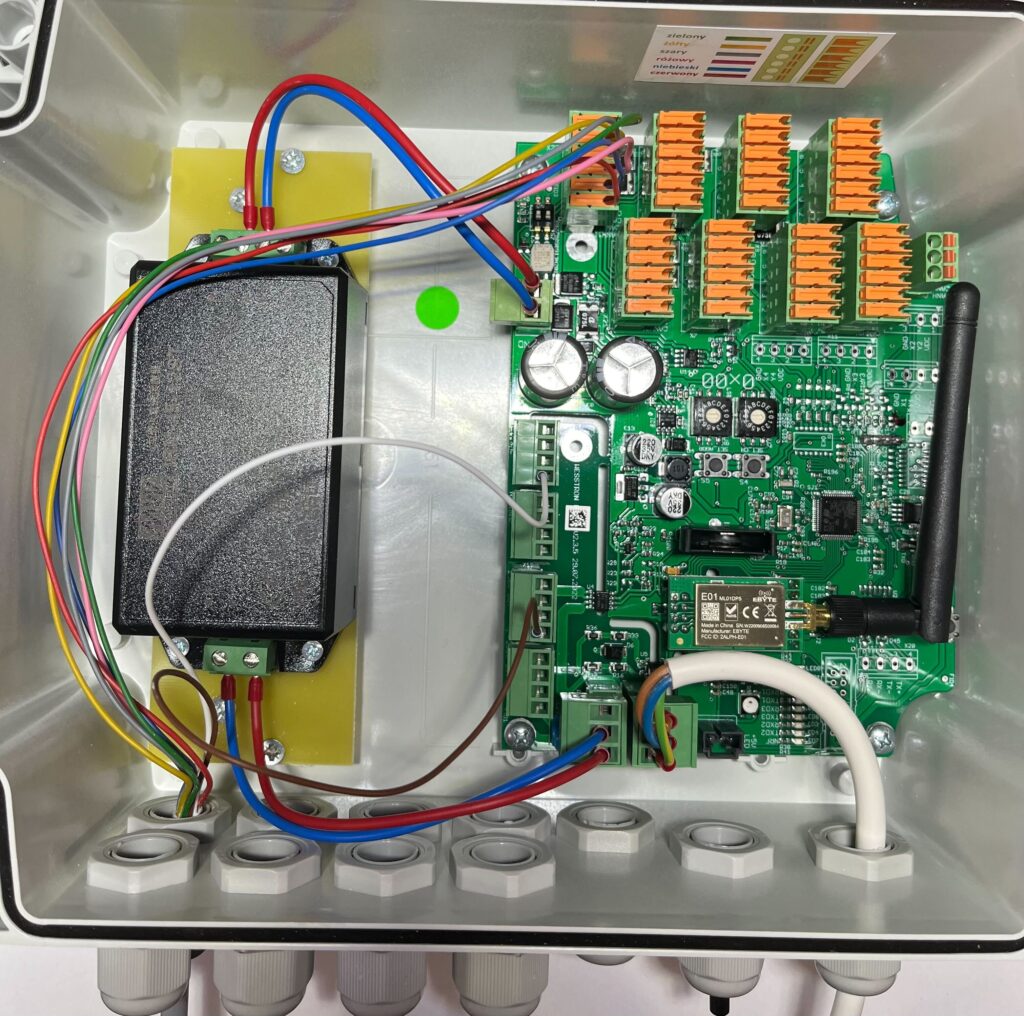
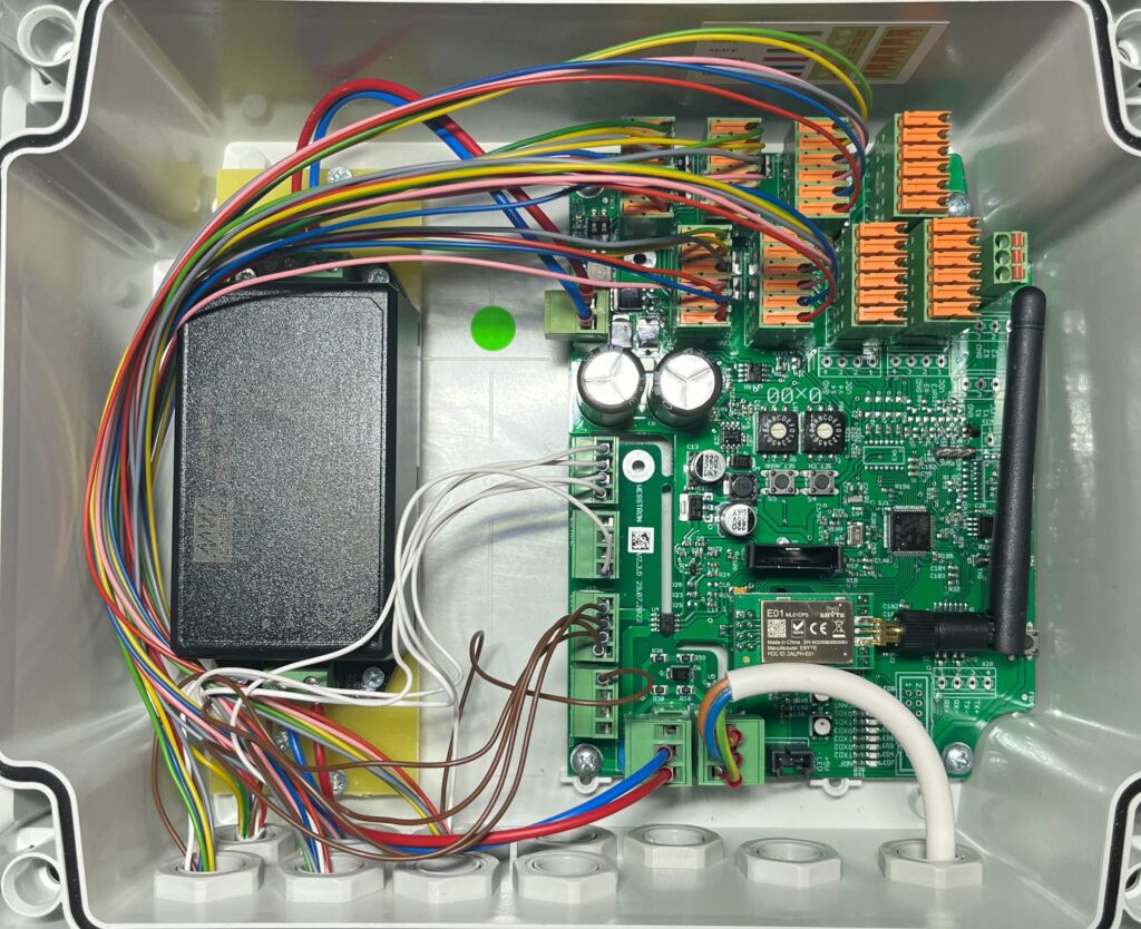
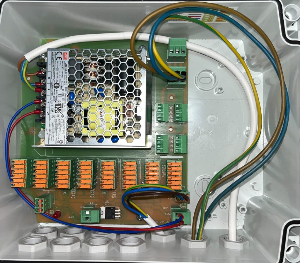
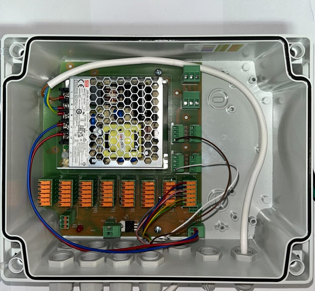
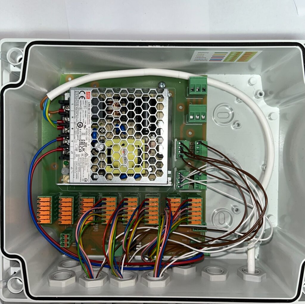
After connecting dispenser number 1 Connector should look as shown below.
Follow the steps from Connecting a single dispenser to connect the other dispensers.
Connect dispenser number 2
Connect dispenser number 3
Connect dispenser number 4
Connect dispenser number 5
Connect dispenser number 6
Connect dispenser number 7
Connect dispenser number 8
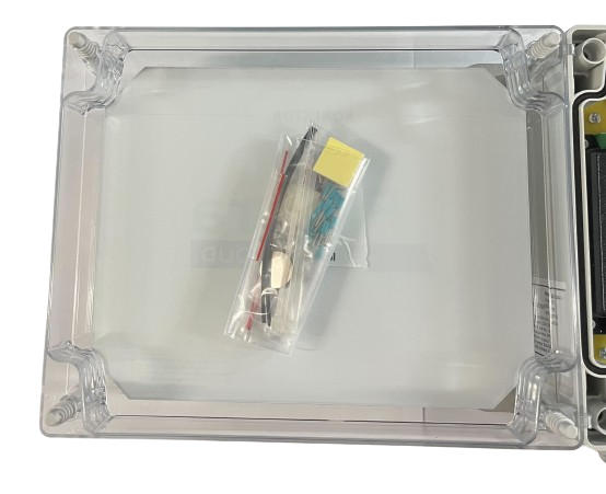
Insert the battery into the Connector
Wiring CAN communication to Connector Extension
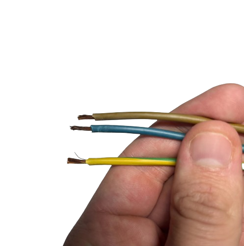
If you are connecting Connector to Connector Extension prepare a 3 x 0.75 mm2 cable. This is a communication cable that allows data exchange between the Connector and Connector Extension.

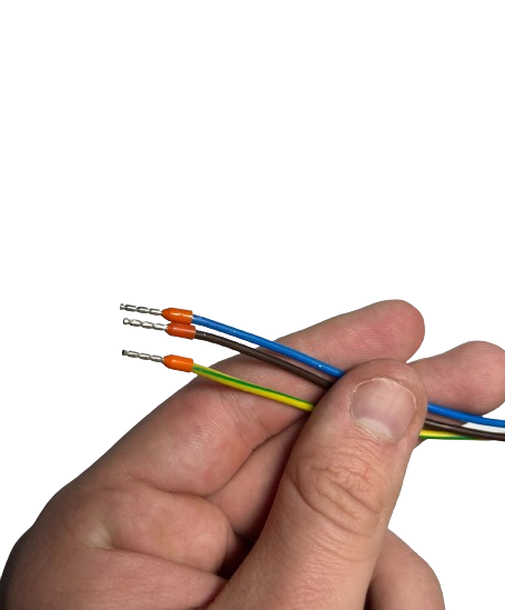
Remove the insulation from the cable, then strip the insulation from each wire.
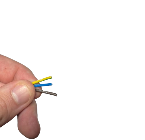
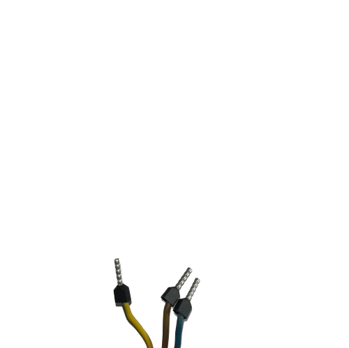
Fit and tighten the collets
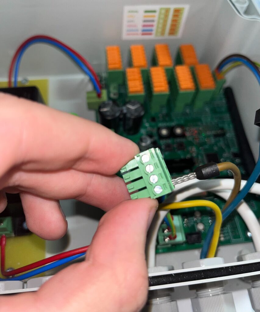
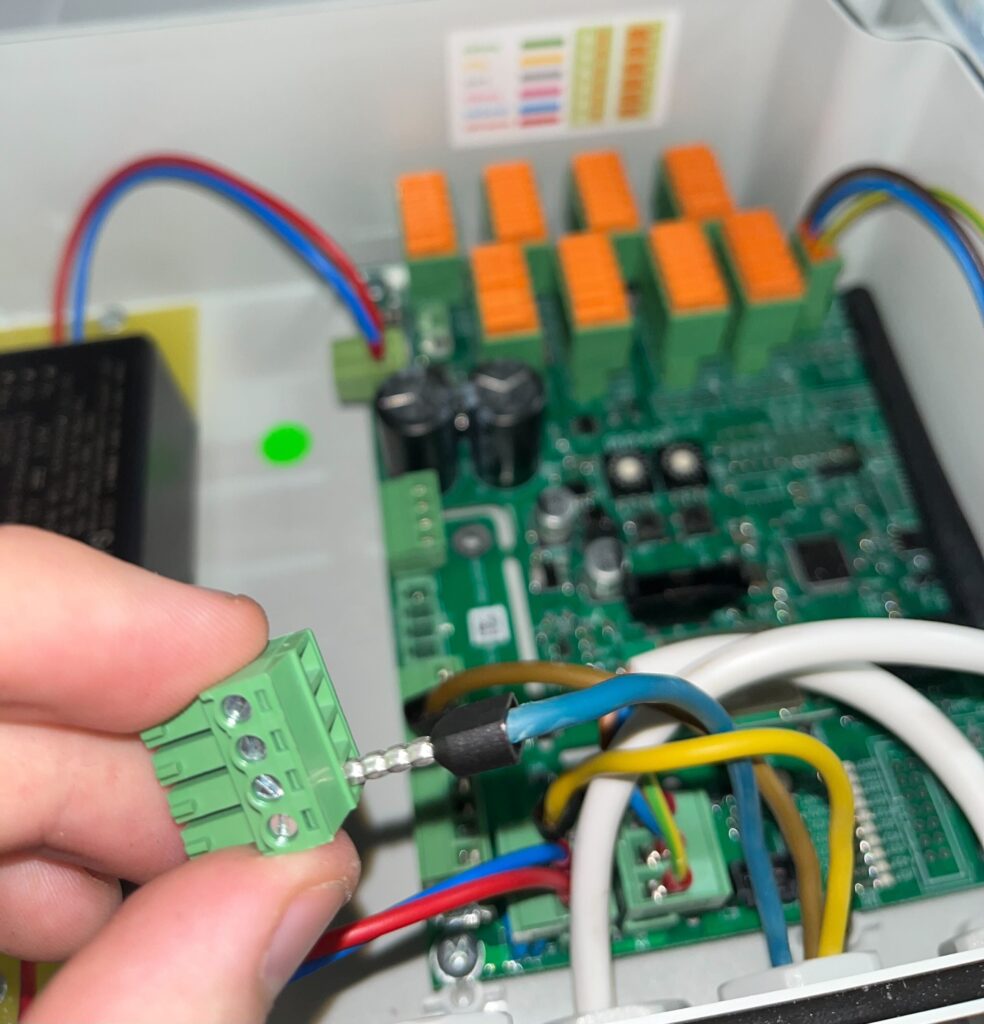
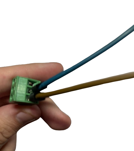
Remove the plug from CAN communication and insert the wires into it, when inserting them slightly press them with a screwdriver.
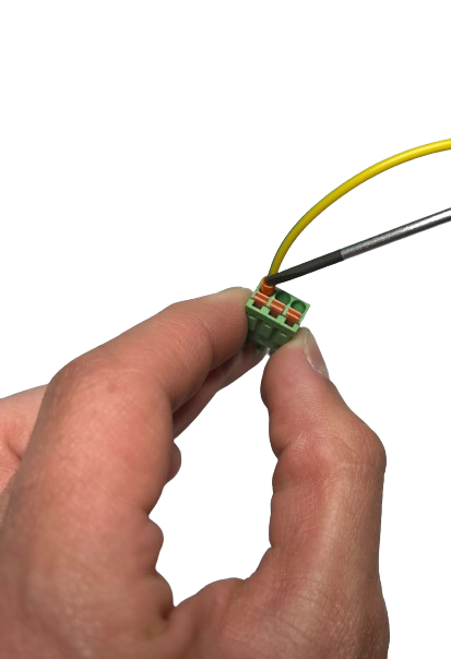
Connect the plug from CAN communication
Connect Connector to Connector Extension with CAN cable
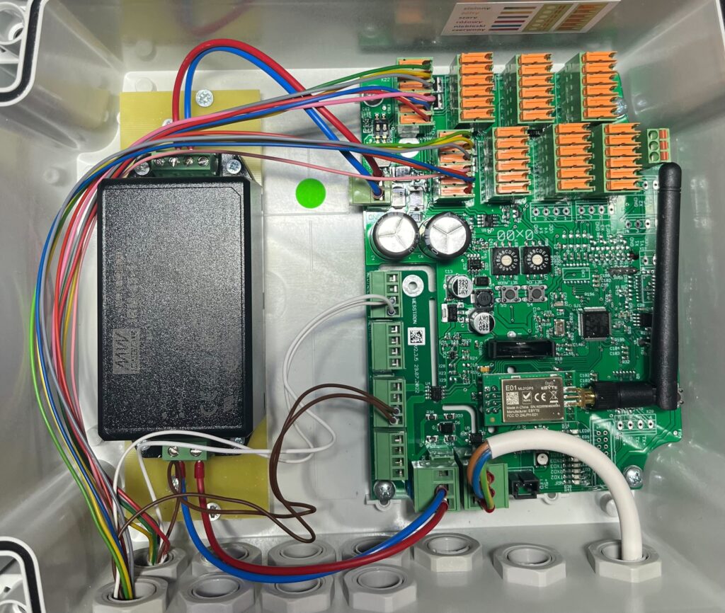
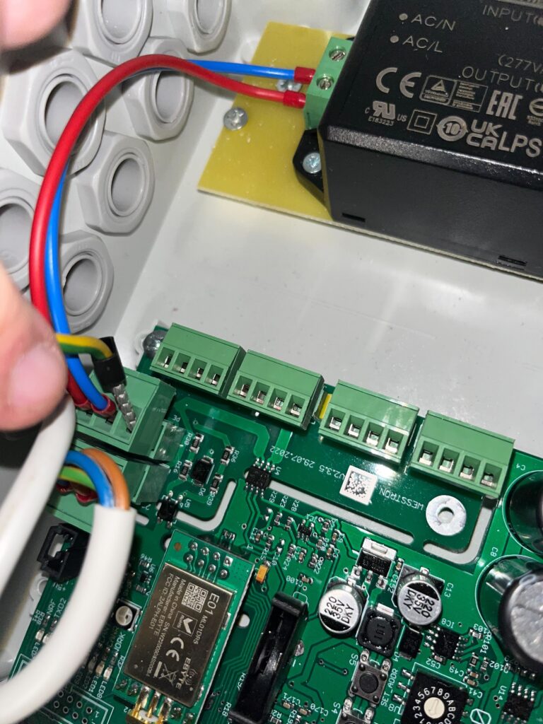
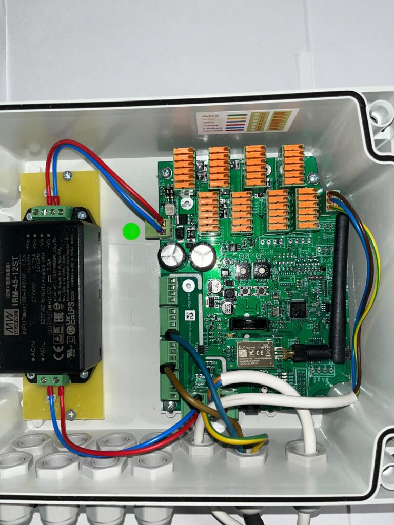
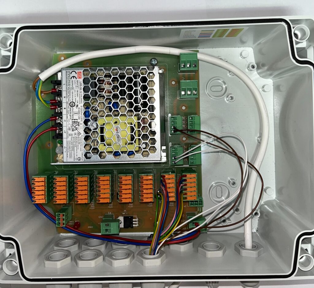
The correct CAN communication connection is shown below.

Connecting dispensers main power to Connector Extension
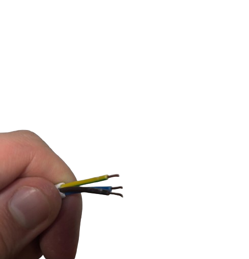
If you are connecting the Connector to the Connector Extension prepare a 3 x 1.5 mm2 cable. This is the cable that powers the motors in the dispensers connected to the Connector Extension.
Remove the insulation from the cable, then strip the insulation from each wire.
Install and tighten the collets.
Insert the green-yellow (protective conductor) wire into the plug with the VDC power supply connected.
Remove the plug from the brown wires (phase wire) and connect the brown wire there.
Remove the plug from the white wires (neutral wire) and connect the blue wire there.
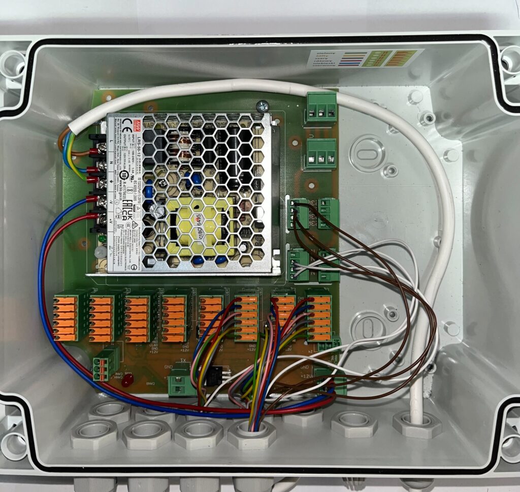
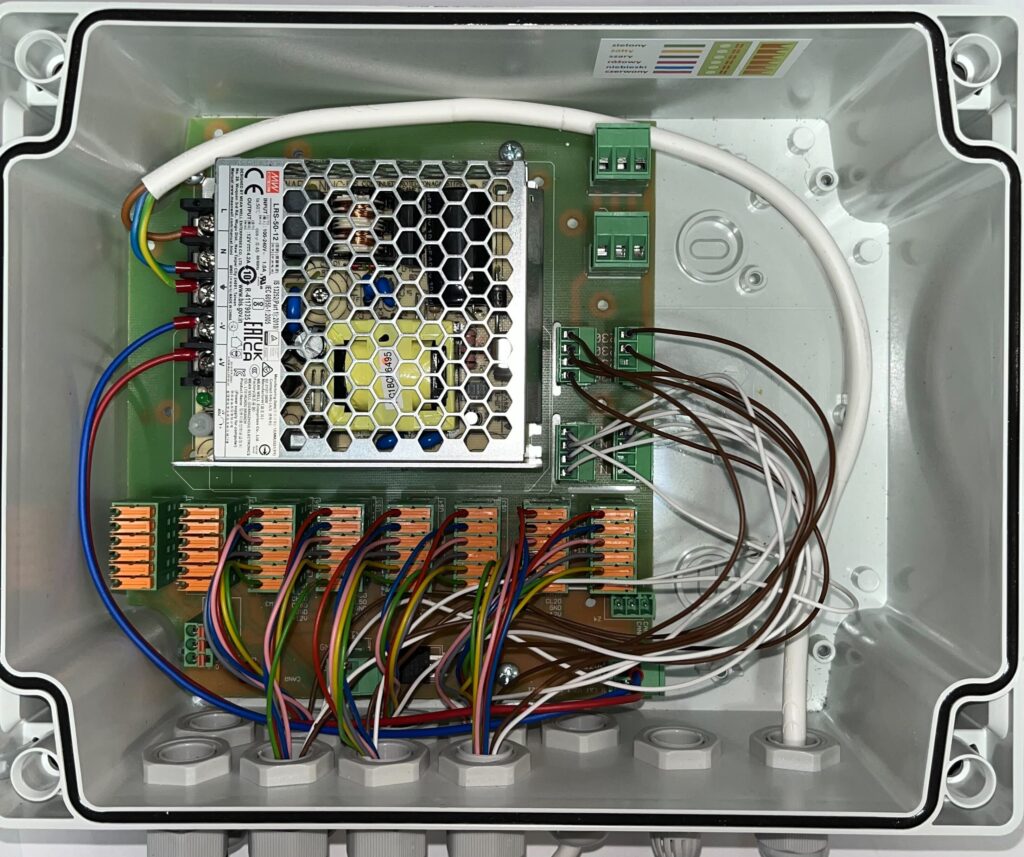
A properly made connection in the Connector should look as shown below.
From the Connector Extension, remove the plug from the dispenser motor power supply and connect the brown wire (phase wire)
Connect the blue wire (neutral wire)
Connect the green-yellow wire (protective wire)

Connect the plug from the dispenser motor power supply
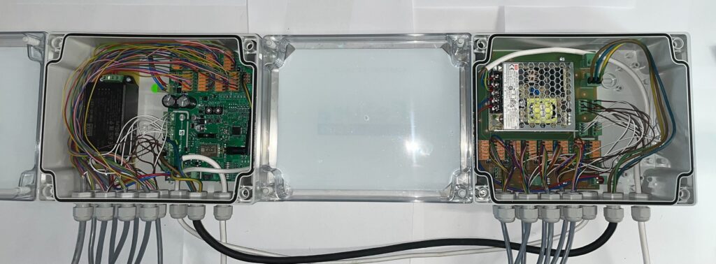
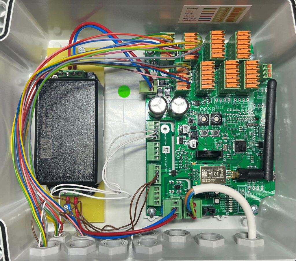
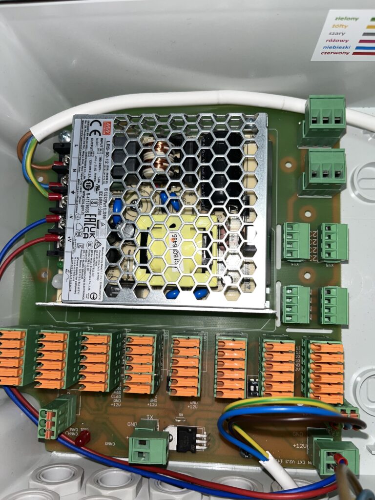
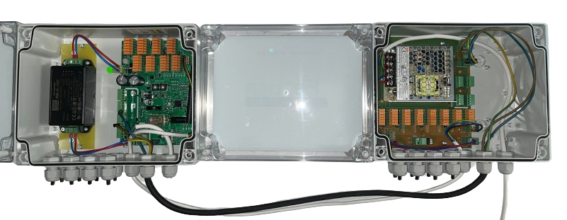
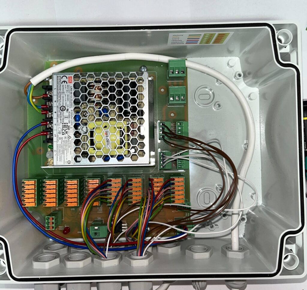
After connecting the power supply to the dispenser motors and CAN communication between the Connector and Connector Extension, the devices should look as shown below.
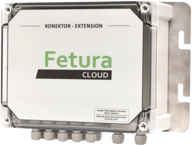
Connector Extension
Connector Extension in the factory state has the main power supply and DC power supply connected and is prepared for connecting dispensers.
Correct operation of Connector Extension requires connection of CAN communication and power supply of dispenser motors directly to Connector. It is described in this article.

Connect dispenser number 1
Connect dispenser number 2
Connect dispenser number 3
Connect dispenser number 4
Connect dispenser number 5
Connect dispenser number 6
Connect dispenser number 7
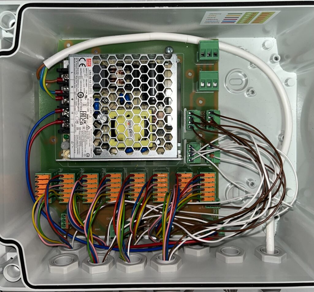
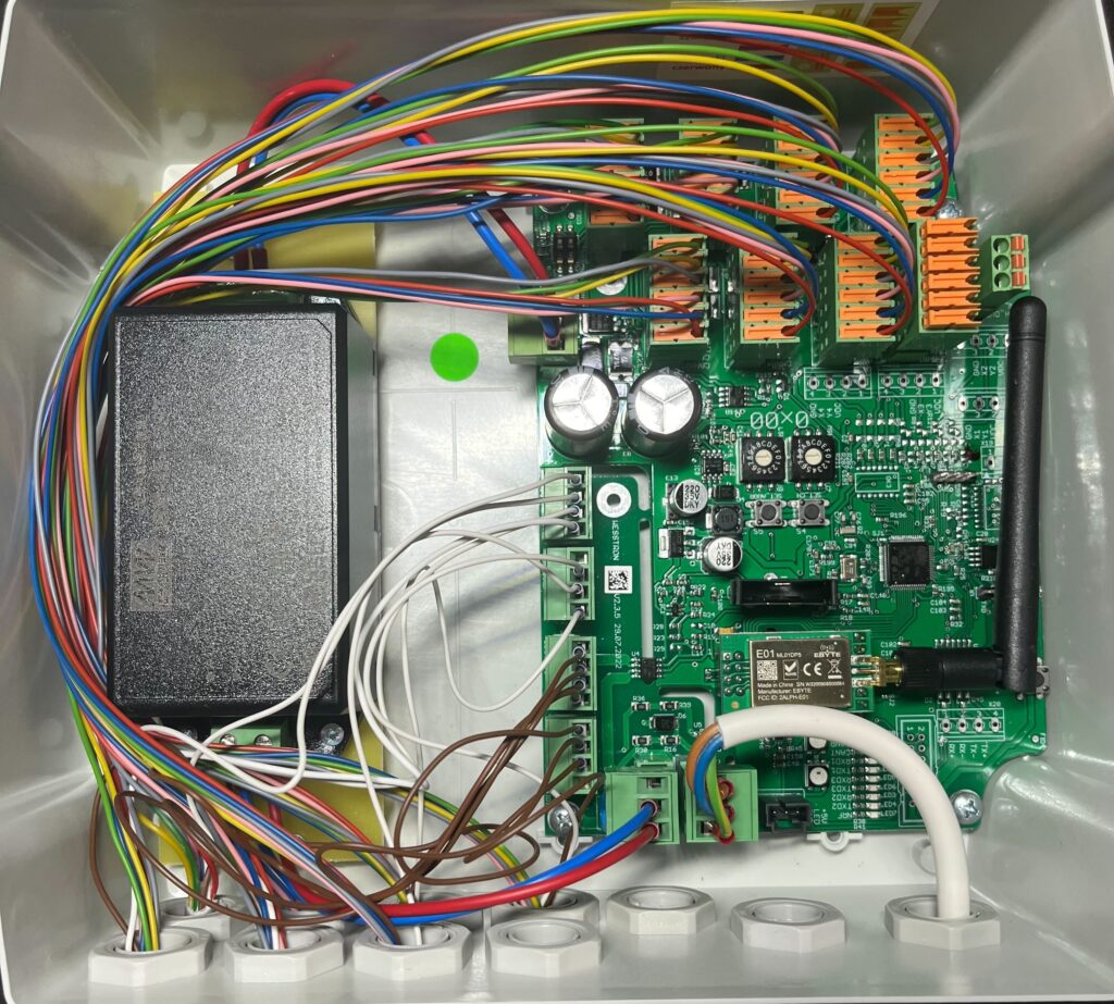
The end result
After connecting all the dispensers, CAN communication and powering the motors in the dispensers, the complete setup looks like the picture below.